
Related Manuals for ABB LVS Digital FC610


Summary of Contents for ABB LVS Digital FC610
- Page 1 D ISTR I B U TI O N S O LU T I O N S LVS Digital FC610 – Feeder monitoring and control User Manual...
- Page 2 This document contains information about one or more ABB products and may include a description of or a ref- erence to one or more standards that may be generally relevant to the ABB products. The presence of any such description of a standard or reference to a standard is not a representation that all the ABB products refer- enced in this document support all the features of the described or referenced standard.
-
Page 3: Table Of Contents
TA BLE O F CO NT ENTS Table of Contents 1 General ............................1 Target Group ..........................1 Use of Warning, Caution, Information and Tip icon ............. 1 Terminology ..........................2 Related Documentation ......................5 Related System Version ......................5 2 Product Information ........................6 Applications .......................... - Page 4 LIST OF F IG UR ES Factory default setting ......................48 User definable reading data ....................49 Appendix A Technical Data ......................50 A.1 Technical specifications ....................... 50 A.2 Characteristics of functions ......................53 A.3 Characteristics of the evaluation function of the quality of supply ........54...
- Page 5 LIST OF F IG UR ES List of Figures Figure 1: Example of using FC610 in a 3-phase feeder ................. 6 Figure 2: FC610 basic unit with HMI MP56, MP53 .................. 7 Figure 3: DIN-rail mounting and removing of FC610 basic unit ............8 Figure 4: Installation of HMI MP53/56 .....................
-
Page 6: General
TARG ET GR OUP G ENER A L General Target Group The manual is primarily intended for those requiring information on the applications of FC610 for the purpose of understanding, engineering, wiring & operating the product. It is assumed that the user has a basic knowledge of physical and electrical fundamentals, elec- trical wiring practices and electrical components. -
Page 7: Terminology
61439-1 gear The digital solution based on low-voltage switch- LVS Digital gear CMES ABB Ability™ Condition Monitoring for electrical systems MConfig-G Configuration and parameterization tool for ABB LVS Digital smart devices including FC610 MODBUS RTU Fieldbus communication protocol based on serial... - Page 8 T ERM IN OLOGY G ENER A L Abbreviation Term Description RS485 Communication interface standard from EIA (Elec- tronics Industries Association, USA), operating on voltages between 0V and +5V. RS-485 is more noise resistant than RS-232C, handles data trans- mission over longer distances, and can drive more receivers.
- Page 9 T ERM IN OLOGY G ENER A L Abbreviation Term Description Power factor Vector Under periodic conditions, ratio of the vector of the active power to the apparent power Voltage dip Temporary reduction of the voltage magnitude at a point in the electrical system below a threshold Voltage swell Temporary increase of the voltage magnitude at a point in the electrical system above a threshold...
-
Page 10: Related Documentation
1TNC928243 Modbus TCP Converter MS572 User Guide • 1TGC908020 LVS Digital Data Description FC610 • 1TGC908001 ABB Ability Condition Monitoring for Electrical System-CMES User Man- Related System Version The content of this document is related to FC610 products with the following hardware and firmware version release. -
Page 11: Product Information
FC610 is part of ABB LVS Digital smart devices family and fully integrated to LVS Digital plat- form via Modbus RTU directly or Modbus TCP through MS572, the digital network converter. -
Page 12: Product Description
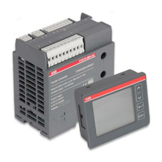
PR OD UCT INFOR MATI ON Product Description FC610 is the smart feeder unit designed for ABB low-voltage switchgear digital family. The product consists of two main parts, i.e. FC610 basic unit and the operator panel, also known as the HMI. The separately mounted HMI from the basic unit fits perfectly in the low-voltage switchgear modules, enabling safe operation of feeders in front of closed doors and com- partments of the switchboard. -
Page 13: Ordering Types
O RD ER ING T YP ES PR OD UCT INFOR MATI ON Ordering Types Depend on selected HMI type, two FC610 product types and order codes are available as fol- lows: 1TNA928612R3001 FC610 with MP53, 110-240Vac supply, Modbus RTU 1TNA928612R6001 FC610 with MP56, 110-240Vac supply, Modbus RTU Installation FC610 basic unit can be easily installed onto standard TS35 DIN-rail. -
Page 14: Figure 5: Installation Dimension And Din-Rail Mounting
I NSTA LLAT IO N PR OD UCT INFOR MATI ON Installation dimension (W X H X D): Basic unit 60 mm x 98 mm x 103 mm HMI unit MP53 (front) 91 mm x 75 mm x 29.3 mm (cut-out) 84 mm x 68 mm x 29.3 mm HMI unit MP56 (front) -
Page 15: Figure 6: Screw Mounting Of Fc610 Basic Unit
I NSTA LLAT IO N PR OD UCT INFOR MATI ON Figure 6: Screw mounting of FC610 basic unit Figure 7: Front panel cut-out dimension of MP53 Figure 8: Front panel cut-out dimension of MP56 1T N C928 25 0M0 201... -
Page 16: Wiring Connections
WIR IN G CO N N ECTIO N S PR OD UCT INFOR MATI ON Wiring connections 2.5.1 Terminal blocks Figure 9: FC610 basic unit terminals description Number Block function Description CT inputs (lead through) Current input by lead through the CT Voltage input Voltage supply Auxiliary power supply... -
Page 17: Figure 10: Fc610 Basic Unit Top View Terminal Layout
WIR IN G CO N N ECTIO N S PR OD UCT INFOR MATI ON Figure 10: FC610 basic unit top view terminal layout Terminal name Function Description L, N Power supply 110-240 VAC R0a, R0b Relay output 24 to 110 VDC, 110 to 240 VAC DI0...DI1 Digital inputs 24 VDC... -
Page 18: Wiring Connections
WIR IN G CO N N ECTIO N S PR OD UCT INFOR MATI ON 2.5.2 Wiring connections FC610 generates a 24 VDC output internally for digital inputs. The maximum load of the inter- nal supply is 100mA@240 VAC input or 50mA @ 110 VAC input of power supply. Figure 11: 24 VDC power output One relay output is available for general fault indication by default. -
Page 19: Figure 14: Dis Supplied By External 24 Vdc
WIR IN G CO N N ECTIO N S PR OD UCT INFOR MATI ON For LVS Digital feeder applications FC610 is typi- cally used to indicate the status and the com- mon fault of the main switching device in addi- tion to the measurement values. -
Page 20: Figure 16: Voltage Measurement Direct Connection
WIR IN G CO N N ECTIO N S PR OD UCT INFOR MATI ON Voltage measurement of FC610 is through the voltage input connections. The maximum di- rect input system voltage is 690 VAC (phase to phase) with 15 % fluctuation. External PT should be used for higher voltage measurement. -
Page 21: Figure 18: Current Measurement Single Phase Connection
WIR IN G CO N N ECTIO N S PR OD UCT INFOR MATI ON Current measurement of FC610 is via a built-in 3-phase CT which is rated at 1 A or 5 A selectable through configuration. An external CT with a secondary rated 1 A or 5 A which is wired through FC610 CT inputs, is usually required in an application. -
Page 22: Product Functions
FC610 provides a complete set of measurement and moni- toring data for the plant operators. With the connectivity to the communication network and the leverage of ABB Ability CMES Condition Monitoring, it assists the plant operator further to set up energy management and asset management strategies. -
Page 23: Measurements
M EA SUR EM ENTS PR OD UCT FU NCTI ONS Measurements Description Range Accuracy (accord. to IEC 61557-12) Voltage U1 30 to 400 VAC ph/n Voltage U2 30 to 400 VAC ph/n Voltage U3 30 to 400 VAC ph/n Voltage U12 50 to 690 VAC ph/ph Voltage U23... -
Page 24: Energy Analysis
EN ERGY ANA LYS IS PR OD UCT FU NCTI ONS Energy analysis 3.2.1 Energy Description Range Accuracy (accord. to IEC 61557-12) Active energy import Ea + 0 to 99999999 kWh Active energy export Ea - 0 to 99999999 kWh Reactive energy import ErV + 0 to 99999999 kvarh Reactive energy export ErV -... -
Page 25: Maximum And Average Demand Values
EN ERGY ANA LYS IS PR OD UCT FU NCTI ONS 3.2.2 Maximum and average demand values In addition to the measured values listed above, FC610 provides demand values to assist the operator to carry out energy consumption analysis and achieve increase in energy efficiency. Demand value is the time-integrated value of the measured values. -
Page 26: Power Quality
P OWER QUA LIT Y PR OD UCT FU NCTI ONS Power quality 3.3.1 Harmonics measurement Harmonics refers to the amount of electricity contained in the current that is an integral mul- tiple of the fundamental (i.e., 50 Hz or 60 Hz). FC610 measures total harmonic distortions as well as individual harmonics up to 31st harmonic. -
Page 27: Voltage Unbalance Supervision
P OWER QUA LIT Y PR OD UCT FU NCTI ONS Current unbalance supervision settings Value range 0=Disable 1=Enable Default value Threshold Value range 50-90 % Defaults value 50 % Step value Hysteresis Value range 0-10 % Default value Step value 3.3.3 Voltage unbalance supervision FC610 monitors unbalanced voltage and voltage unbalanced condition. -
Page 28: Voltage Dip Supervision
P OWER QUA LIT Y PR OD UCT FU NCTI ONS 3.3.4 Voltage dip supervision Voltage dip is the condition of voltage dropping temporarily under the threshold level due to an unexpected electrical system network disturbance. The dip threshold and hysteresis volt- age settings are a percentage of the system rated voltage Un. -
Page 29: Voltage Swell Supervision
P OWER QUA LIT Y PR OD UCT FU NCTI ONS 3.3.5 Voltage swell supervision Voltage swell is the condition when the voltage in the electrical system temporarily increase above a threshold. The swell threshold and hysteresis voltage settings are a percentage of the system rated volt- age Un. -
Page 30: Voltage Interruption Supervision
P OWER QUA LIT Y PR OD UCT FU NCTI ONS 3.3.6 Voltage interruption supervision Voltage interruption is a special case of voltage dip. It provides a second level setting in addi- tion to voltage dip supervision to assist the operator in network analysis. The interruption threshold and hysteresis voltage settings are a percentage of the system rated voltage Un. -
Page 31: Load Supervision
LOA D SUP ERVI SIO N PR OD UCT FU NCTI ONS Load supervision 3.4.1 Over current supervision FC610 monitors over current condition of the connected load by issuing an alarm message. The over current function in FC610 is designed for supervision purpose only and should not be used to replace any over current protection device. -
Page 32: Phase Sequence Supervision
LOA D SUP ERVI SIO N PR OD UCT FU NCTI ONS 3.4.2 Phase sequence supervision FC610 monitors phase sequence of the voltage or current to prevent loss due to wiring errors of the connected load. Before FC610 detects the current, the phase sequence protection is based on voltage. -
Page 33: Status And Condition Monitoring
LOA D SUP ERVI SIO N PR OD UCT FU NCTI ONS 3.4.3 Status and condition monitoring FC610 provides status monitoring of the connected devices through digital IOs in addition to electrical measurements. FC610 also provide condition data of the connected load and switching device for service and maintenance purpose. -
Page 34: Data Recording And Logs
DATA R ECORD I NG AN D LO GS PR OD UCT FU NCTI ONS Data recording and logs Data recording and logs in FC610 √ Single last alarm with time stamp √ Single last operation with time stamp √ Sequence of events (SOE)up to 256 events √... -
Page 35: Figure 23: Example Of Voltage Dip Curve U1- The Event Completes Within 120 Samples Time
DATA R ECORD I NG AN D LO GS PR OD UCT FU NCTI ONS Event curve FC610 records events triggered by voltage dip, voltage swell, Interruption, over current through event curves. Current and voltages curves including I1, I2, I3, U1, U2, U3, U12, U23, and U31 of each triggered event are recorded in FC610. - Page 36 DATA R ECORD I NG AN D LO GS PR OD UCT FU NCTI ONS Load curve FC610 records load profile curves for P1, P2, P3, Q1, Q2, Q3, S1, S2, S3 and P, Q, S, PF for a fixed period.
-
Page 37: Connectivity
To integrate FC610 into a Modbus TCP network the generic ABB Modbus RTU/TCP converter MS572 can be used. FC610 is fully integrated to ABB LVS Digital network via Modbus RTU as well as Modbus TCP. Figure 25: Example for LVS Digital integration with FC610 via Modbus RTU... -
Page 38: Hmi Mp53/Mp56
HMI MP53/MP56 FC610 provides HMI panel MP53/56 for local monitoring, operation and configuration. MP53 is designed to be fit to the compact module front door of ABB LVS switchgear. MP56 provides a bigger LCD screen with a better visual option. -
Page 39: Notification Icons
N OTI FI CAT IO N I CO NS HM I MP53/MP 56 Notification icons Icon Description Indication of 1 quadrant Energy Import, Energy Export Alarm is active MP Communication active Parameter configuration in progress Main display pages Figure 29: Main display page 1T N C928 25 0M0 201... -
Page 40: Navigate Through Display Groups
MA I N DI SP LAY PAGES HM I MP53/MP 56 4.3.1 Navigate through display groups Parameters are grouped into 9 main display groups for easy navigation. Long pressing the scroll button up or down changes the display group. The display of which parameter groups are customizable in HMI panel. How to select the pa- rameter groups to display is explained in configuration section. -
Page 41: Navigate Through Each Display Page
MA I N DI SP LAY PAGES HM I MP53/MP 56 4.3.2 Navigate through each display page Under each display group, parameters are displayed in separate pages. Short press the scroll buttons to navigate through each display page. Figure 31: Navigate through display pages under each group Display group Page no. - Page 42 MA I N DI SP LAY PAGES HM I MP53/MP 56 MAX and AVG value 1 Max current I Max current I (%) =Max I /In*100 % Max Earth Fault Current I Ave△N Max phase voltage U Max line voltage U Max Frequency F (Hz) Max P...
- Page 43 MA I N DI SP LAY PAGES HM I MP53/MP 56 Device status Main switch status off/on/fault Digital input 1 status: on/off Digital input 2 status: on/off Run time Maintenance Stop time Insert times parameters changed times 1T N C928 25 0M0 201...
-
Page 44: Alarm Messages
CO NF IG UR AT IO N PAG ES HM I MP53/MP 56 4.3.3 Alarm messages Alarm message is displayed on the bottom of the display page with an alarm indication icon whenever there is an active alarm active. Alarm message Alarm description Alarm condition OVER_I... -
Page 45: Fc610 Device Setting
CO NF IG UR AT IO N PAG ES HM I MP53/MP 56 4.4.1 FC610 device setting This is the setting related to FC610 device which includes: • Communication parameters (baud rate, slave address etc.) • Display panel (LCD setting and password) •... -
Page 46: Figure 32: How To Change Default Password
CO NF IG UR AT IO N PAG ES HM I MP53/MP 56 An example is given below to change password from 1111 to 0000. Figure 32: How to change default password 1T N C928 25 0M0 201... -
Page 47: Figure 33: Turn Off The Voltage, Frequency Display Group
CO NF IG UR AT IO N PAG ES HM I MP53/MP 56 The example below shows how to turn on/off the display groups of parameters : Figure 33: Turn off the voltage, frequency display group 1T N C928 25 0M0 201... -
Page 48: Feeder Information Setting
CO NF IG UR AT IO N PAG ES HM I MP53/MP 56 4.4.2 Feeder information setting This is the fundamental information of the feeder which include, • Feeder control • Feeder Information Level 1 Level 2 Level 3 Value range 1-10000 A (PARA: Parameters) (FCON: Feeder... -
Page 49: Supervision Functions Setting
CO NF IG UR AT IO N PAG ES HM I MP53/MP 56 4.4.3 Supervision functions setting Supervision functions including power quality supervision and load supervision are, Over current supervision, current unbalance supervision, voltage unbalance supervision, volt- age dip supervision, voltage swell supervision, voltage interruption supervision and phase sequence supervision. -
Page 50: Figure 34: Change The Hysteresis Value
CO NF IG UR AT IO N PAG ES HM I MP53/MP 56 (U-IS: Voltage (FUNC: Function) Interruption (Disable/Enable) Supervision) 95 %-100 % (THSH: Threshold) 0 %-10 % (HYST: Hysteresis) (PSS: Phase (FUNC: Function) Sequence (Disable/Enable) supervision) The example below shows how to change the value from 1 % to 4 % of the “Hysteresis” ) under “Voltage Unbalance Supervision”... -
Page 51: Demand Integration Time Setting
CO NF IG UR AT IO N PAG ES HM I MP53/MP 56 4.4.4 Demand integration time setting The demand integration time in FC610 are selectable from 2 s, 10 s, 5 min, 8 min, 10 min, 15 min, 20 min, 30 min and 60 mins. The integration time is calculated by the sliding method. The slid- ing time interval is 1 second when the integration time is selected as 2 or10 seconds. -
Page 52: Read Production Version
CO NF IG UR AT IO N PAG ES HM I MP53/MP 56 4.4.6 Read production version The user can view the firmware version of the products including the bootloader of FC610, the application of FC610, MP53/56 and external modules if connected. The firmware of FC610 usually refers to the application firmware, i.e., which may be required to be updated or upgraded due to bug fixing or feature improvements. -
Page 53: Configuration
CO NF IG UR AT IO N O F FC610 CO NF IG UR AT IO N Configuration Configuration of FC610 Parameters of FC610 are expected to be configured via HMI panel MP53 or MP56 which is de- scribed in section 4. In case of firmware updating or reading event curves, MConfig-G software must be used. -
Page 54: User Definable Reading Data
U S ER D EFI NAB LE R EAD ING DATA CO NF IG UR AT IO N Parameters Range Factory setting External PT Used** Disable Demand integration time (I, U,F,P) 2s,5s,5m,8m,10m,15m,20m,30m,60m 10 mins Event curves record point*** 30-70 % 30 % DI/DOs Main switch status... -
Page 55: Appendix A Technical Data
A .1 T ECHN I CA L SP ECI FI CATI O NS CO NF IG UR AT IO N — Appendix A Technical Data A.1 Technical specifications Main circuit Nominal voltage 3 X 230/400 VAC (Ph/N) Voltage range 3 X 30 – 400 VAC (Ph/N) Rated insulation voltage 800 VAC Frequency... - Page 56 A .1 T ECHN I CA L SP ECI FI CATI O NS CO NF IG UR AT IO N Auxiliary power supply Rated operational voltage (Ue) 110-240 VAC Voltage operation range 85 %-110 % Ue Rated frequency 50 / 60 Hz Power consumption 16 VA max.
- Page 57 CO NF IG UR AT IO N Electromagnetic environment 1) Equipment in the system comply with EMC requirement of CE / CCC certificate. Power supply system complies with IEC61000-2-1, IEC61000-2-2, especially the sys- tem in which VSD / Frequency Converters are used.
-
Page 58: A.2 Characteristics Of Functions
A .2 CHAR ACT ER ISTI CS O F F U NCT IO NS CO NF IG UR AT IO N A.2 Characteristics of functions Function symbols Measuring range Function performance Other complementary class according to characteristics IEC 61557-12 2 % to 120 % In 2 % to 120 % In 2 % to 120 % In 0 to 99999999 kWh... -
Page 59: Characteristics Of The Evaluation Function Of The Quality Of Supply
A .3 CHA R ACT ERIST I CS O F TH E EVA LUAT IO N F UNCTI ON OF TH E Q UA LI T Y O F SUPP LY CO NF IG UR AT IO N A.3 Characteristics of the evaluation function of the quality of supply Function symbols Measuring range Function perfor- Other comple-... - Page 60 — Revision History Revi- Page(s) Description of change Date sion M0201 Initial Edition 2021-01...
- Page 61 — Publication Editor: Electrification-Distribution Solutions Division ABB (China) Limited No.885, FangShanXiEr Road, Xiang'an District, Xiamen, Fujian, 361101 P.R.China Local Contacts on http://www.abb.com/mns © Copyright 2021 ABB. All rights reserved. Specifications subject to change without notice.
Need help?
Do you have a question about the LVS Digital FC610 and is the answer not in the manual?
Questions and answers