
Subscribe to Our Youtube Channel
Related Manuals for FuzzDog Quack Machine


Summary of Contents for FuzzDog Quack Machine
- Page 1 Quack Machine Dr Quack Auto Envelope Filter Contents of this document are ©2018 Pedal Parts Ltd. No reproduction permitted without the express written permission of Pedal Parts Ltd. All rights reserved.
- Page 2 Schematic + BOM D1,2 Red 3mm LED 1N4148 2N5457 2N3904 2.2M* 100R TL072 RANGE 20/25KB** SENS 100KB 470K *In most cases R6 will be good for the gain setting. If you 470K prefer you can use a smaller value and add a trimmer in the GAIN spot to adjust to taste.
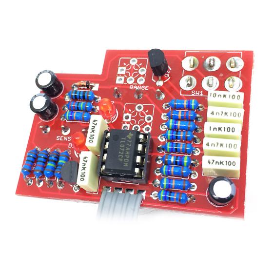
- Page 3 The power and signal pads on the PCB conform Solder the pots last, as once they’re in place to the FuzzDog Direct Connection format, so you’ll have no access to the pads beneath can be paired with the appropriate them.The best way to get the pots lined up is daughterboard for quick and easy offboard to first solder one pin of each.
- Page 4 Test the board! BATTERY 9V GND Your nice, new circuit board INCLUDING WIRED POTS!!!! UNDER NO CIRCUMSTANCES will troubleshooting help be offered if you have skipped this stage. No exceptions. Once you’ve finished the circuit it makes sense to test is before starting on the switch and LED wiring.
- Page 5 Wire it up (if using a daughterboard please refer to the relevant document) BOARD BOARD INPUT BOARD BOARD BOARD BOARD LED+ BOARD BOARD BATTERY NOTE: Chances are you’re using a 1590B enclosure and can’t fit a battery in there. If so, just ignore the battery and Ring of the IN jack shown. Wiring shown above will disconnect the battery when you remove the jack plug from the input, and also when a DC plug is inserted.
- Page 6 32mm This template is a rough guide only. You should ensure correct marking of your enclosure before drilling. You use this template at your own risk. Pedal Parts Ltd can accept no responsibility for incorrect drilling of enclosures. FuzzDog.co.uk...
Need help?
Do you have a question about the Quack Machine and is the answer not in the manual?
Questions and answers