Table of Contents
Advertisement
Quick Links
Advertisement
Table of Contents

Related Manuals for MFJ MFJ-1795W


Summary of Contents for MFJ MFJ-1795W
- Page 1 WARC Band Portable Antenna Model MFJ-1795W INSTRUCTION MANUAL CAUTION: Read All Instructions Before Operating Equipment MFJ ENTERPRISES, INC. 300 Industrial Park Road Starkville, MS 39759 USA Tel: 662-323-5869 Fax: 662-323-6551 COPYRIGHT 2006 MFJ ENTERPRISES, INC. VERSION 1A...
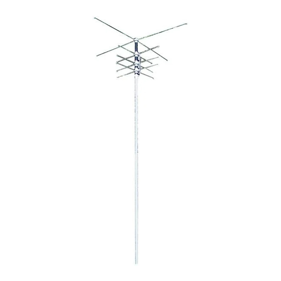
- Page 2 MFJ-1795W Vertical Antenna Instruction Manual MFJ-1795W 60 Meter Capacitance Spokes (8) WARC Band & Loading Coil Vertical Antenna 30 Meter (4) 17 Meter (4) 12 Meter (4) Always Follow Assembly 1” x 30” 30 x 1” Tubing Instructions!! 5’ x1 1/8” Tubing...
-
Page 3: Choosing A Location For The Antenna
Instruction Manual INTRODUCTION The MFJ-1795W HF antenna was designed to provide portable or permanent WARC Band operation from restricted locations. When combined with the MFJ Ground-Coupled™ Portable Antenna Base or other suitable grounding system, such as radial system, the result is a small vertical antenna under 10 feet in height. -
Page 4: Antenna Height
INSTALLATION The MFJ-1795W was designed as a low profile, portable antenna. When combined with the MFJ Ground-Coupled™ Portable Antenna Base the antenna will provide permanent or portable communications. This is an ideal antenna for restricted locations. However, the antenna installation MUST be protected with non-metallic fencing to provide personal safety and to prevent antenna damage. -
Page 5: Safety Precautions
For installation you will need some additional items not supplied with the antenna installation kit. [ ] Quality low-loss 50-Ohm coax with a PL-259 to go from the antenna to the transmitter. [ ] Either a SWR meter or Analyzer (MFJ-259B, 269) SAFETY PRECAUTIONS:... -
Page 6: Assembly And Installation Procedure
MFJ-1795W Vertical Antenna Instruction Manual WARNING: You can be killed if the antenna, feed-line, or the equipment used to install the antenna accidentally contacts any utility lines. Never install an antenna near power lines! 1. Be careful while carrying the antenna. It is heavy enough to cause you to lose your balance if it is handled too casually or if the capacitance spokes become entangled in obstructions. - Page 7 MFJ-1795W Vertical Antenna Instruction Manual [ ] 6. Now take the 1.0” x 30” piece of aluminum and place at a minimum 2 inches into the long aluminum element (5’ x 1 1/8”). The end of the long (5’) piece used should be the one without the hole drilled in it.
- Page 8 MFJ-1795W Vertical Antenna Instruction Manual 6-32” screw Loading Coil Assembly Figure 3 IMPORTANT: Do not use a high torque electric screwdriver to mount the capacitance spokes. The screw heads will be sheared off if too much torque is applied. [ ] 13. Install four 36” capacitance spokes in the next sets of rings (30M). Again, tighten these spokes as was done in step 9.
- Page 9 [ ] 16. Double check the tightness of all the hardware you installed. Then, mount the antenna on the short temporary tuning mast or the MFJ Ground Coupled Portable Antenna Base. [ ] 17. Secure the mounting bracket to the fiberglass insulator as shown in Figure 5. Make sure the antenna mast does not contact the U-bolts.
- Page 10 The antenna base should be assembled using the instructions supplied with the unit. The following instructions will explain the installation of the MFJ-1795W to the antenna base. [ ] 1. The U-bolts should be attached to the base through the holes as indicated in Figure 5.
- Page 11 MFJ-1795W Vertical Antenna Instruction Manual SO-239 Bushing U-bolts Anetnna Base Figure 6 [ ] 3. The plastic bushing supplied in the parts should be placed in the hole under the SO-239 connector. [ ] 4. Now the 15” piece of insulated wire should be passed through the plastic bushing to the antenna feed-point.
- Page 12 100 KHz) and is the most sensitive to adjustments. The entire antenna must be accessible during initial tuning and testing. If the MFJ Ground Coupled™ Portable Antenna Base is used, attach the antenna to the base and place it in a location away from buildings or other objects that could affect the measurements.
- Page 13 MFJ-1795W Vertical Antenna Instruction Manual The SWR can be measured by using a transmitter and SWR bridge or an SWR Analyzer. The measuring device should be connected to the antenna with a reasonably short length of high quality 50-Ohm coaxial cable. If using a transceiver and SWR meter, set the transceiver to the lowest possible power to take measurements.
-
Page 14: Grounding Considerations
MFJ-1795W Vertical Antenna Instruction Manual CAUTION: Be careful when working with the capacitance spokes. Contact with the sharp ends could result in injury or damage. When shortening the capacitance spokes be certain to replace the protective caps after each adjustment. -
Page 15: Maintenance
MFJ Technical Service at 662-323-0549 or the MFJ Factory at 662-323-5869. You will be best helped if you have your unit, manual and all information on your station handy so you can answer any questions the technicians may ask. -
Page 16: Full 12-Month Warranty
MFJ Enterprises, Inc. warrants to the original owner of this product, if manufactured by MFJ Enterprises, Inc. and purchased from an authorized dealer or directly from MFJ Enterprises, Inc. to be free from defects in material and workmanship for a period of 12 months from date of purchase provided the following terms of this warranty are satisfied.
Need help?
Do you have a question about the MFJ-1795W and is the answer not in the manual?
Questions and answers