
Related Manuals for Safe Fleet DH4C


Summary of Contents for Safe Fleet DH4C
- Page 1 DH4C 4-Channel DVR Installation Guide © Safe Fleet | 2020 | All rights reserved | Part #: 700-1213 R1...
- Page 2 — this page left intentionally blank — © Safe Fleet | 2020 | All rights reserved | Part #: 700-1213 R1...
-
Page 3: Table Of Contents
Speed Settings......42 DH4C Operation....11 GPS Fencing.. -
Page 4: System Components
DVR keys for securing the SD card slot. Configuration equipment: • For on-screen configuration: portable video monitor and mouse. • For browser access configuration: laptop and an Ethernet cable. © Safe Fleet | 2020 | All rights reserved | Part #: 700-1213 R1 p. 4... -
Page 5: System Diagram
4. Only one of the Smart-Reach Lite, the Smart-Reach Cellular modem, or a laptop can connect to the POE-LAN input at a time. 5. An optional Video Monitor can be used from the video output located on the front panel. © Safe Fleet | 2020 | All rights reserved | Part #: 700-1213 R1 p. 5... -
Page 6: Dh4C Installation
A single 4-inch diameter loop is sufficient. WARNING It is your responsibility to avoid damaging safety or electrical systems. Ensure you read and understand the DH4C DVR Installation Requirements. If you are not confident in your ability to perform the procedures in this tutorial, please contact Safe Fleet. -
Page 7: Installing The Dvr
For more information, find the DH4C Quick Installation Guide on the Safe Fleet Community, and read the section DH4C Operation in this document. © Safe Fleet | 2020 | All rights reserved | Part #: 700-1213 R1 p. 7... -
Page 8: Installing The Adapter Harness (Optional)
(optional). (5 wires) For more information, see the "System Diagram" on page 5. Unused To RGY Button extn. harness (1 x 5) © Safe Fleet | 2020 | All rights reserved | Part #: 700-1213 R1 p. 8... -
Page 9: Firmware Updates
DH4C Installation Firmware Updates Firmware controls how DVR features operate, including the Playback and Configuration menu displays. Safe Fleet Technical Support may direct you to install a firmware update when new features are added or specific issues are addressed. Firmware Updates Only install firmware updates as directed by Safe Fleet Technical Support. -
Page 10: Hardware Installation Checklist
Click Yes. When the process completes and a message appears, click OK. Exit the Configuration setting menu, and system setup is complete. Fasten and lock the front cover. © Safe Fleet | 2020 | All rights reserved | Part #: 700-1213 R1 p. 10... -
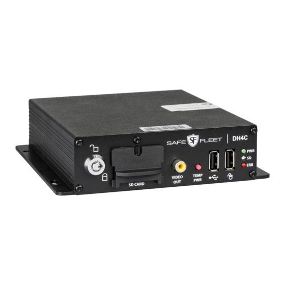
Page 11: Dh4C Operation
6. USB Port supports USB devices used to: • copy video and audio information • export video clips • update DVR firmware • import/export configuration data and archives © Safe Fleet | 2020 | All rights reserved | Part #: 700-1213 R1 p. 11... -
Page 12: Dvr Back Panel Features
In addition to the data transmitted, the POE (Power Over Ethernet) LAN port supplies 12 volts to power accessories such as the Smart-Reach Lite wireless bridge. © Safe Fleet | 2020 | All rights reserved | Part #: 700-1213 R1 p. 12... -
Page 13: Video System Status
If the system is experiencing video loss and not recording, the red light displays. On systems with primary storage consisting of dual media, both media must fail. © Safe Fleet | 2020 | All rights reserved | Part #: 700-1213 R1 p. 13... -
Page 14: Video Flagging
2. Click text or numbers to enter values with the virtual keys. Cancel closes the keyboard without saving changes. 3. When you're done, click Enter to save changes and close the keyboard. © Safe Fleet | 2020 | All rights reserved | Part #: 700-1213 R1 p. 14... -
Page 15: Health Check
WiFi RSSI Relative radio frequency signal strength: the lower the dBm value, the stronger the signal. Reported dBm of between 50-75 indicates a strong signal. © Safe Fleet | 2020 | All rights reserved | Part #: 700-1213 R1 p. 15... -
Page 16: Dh4C Administration
User Guide on the Safe Fleet Community. For full-featured video review, searching, and archiving, we recommend Evidence Manager. The software is supported on a Windows-based computer. For more information, see the Evidence Manager User Guide on the Safe Fleet Community. Using the On-screen Display To use the On-screen Display: 1. - Page 17 LIVE (live mode - not recording) • PLAYBACK (DVR playing locally) • RECORD (normal recording) • ALARM (alarm recording) • V.LOSS (video loss or camera signal loss) © Safe Fleet | 2020 | All rights reserved | Part #: 700-1213 R1 p. 17...
- Page 18 If GPS is connected but the satellite signal is not being received, zeros are displayed. AC (ALARM COUNT) Number of alarms triggered. Resets to 0 when DVR is restarted. Highlights when vehicle ignition is on. © Safe Fleet | 2020 | All rights reserved | Part #: 700-1213 R1 p. 18...
-
Page 19: Working With Video
4. In the center of the Playback View, click the Show/Hide icon. The Playback Toolbar appears. 5. Click the icons to browse video and archive clips. Multi-camera View Playback Toolbar Metadata © Safe Fleet | 2020 | All rights reserved | Part #: 700-1213 R1 p. 19... - Page 20 For more information, see Metadata Details in DH4C Configuration: Title/Display Menu. Show/Hide Playback Tool Bar Shows/hides the playback tool bar. Exit Closes the On-Screen Display © Safe Fleet | 2020 | All rights reserved | Part #: 700-1213 R1 p. 20...
- Page 21 The DVR retrieves a list of recorded video segments containing the specified event type. Select an item from the list, then click Play to view the video captured when the event occurred. © Safe Fleet | 2020 | All rights reserved | Part #: 700-1213 R1 p. 21...
-
Page 22: Dh4C Basic Configuration
Browser requires the proper network configuration to establish a connection, and a browser extension to display the user interface. For more information, find the vMax Web User Guide on the Safe Fleet Community. Plug an RJ-45 Ethernet cable into the back panel LAN port, or connect remotely over a network if you have Smart Reach wireless access. - Page 23 IT administrator. Network Advanced WIFI If the DH4C built-in WIFI is used, enter WIFI settings as instructed by an IT administrator. System Select the audio channel to output from the DVR audio RCA socket.
-
Page 24: Time And Date
Set the date for the DVR. GPS Time Sync If GPS is installed, set this ON to have the system time [OFF] automatically updated when satellites are detected. © Safe Fleet | 2020 | All rights reserved | Part #: 700-1213 R1 p. 24... -
Page 25: Title And Display
If Metadata Display is ON, display the ambient temperature [F], C inside the DVR in degrees. Select F (Fahrenheit) in the USA or C (Celsius) in Canada. © Safe Fleet | 2020 | All rights reserved | Part #: 700-1213 R1 p. 25... - Page 26 Vehicle ignition state (highlighted=ignition on, dimmed=off). Fan failure notification (highlighted=failure, dimmed=normal). G-Sensor (GSN) G Sensor threshold incident (highlighted=threshold exceeded). For more information, see DH4C Configuration: G Sensor Options. © Safe Fleet | 2020 | All rights reserved | Part #: 700-1213 R1 p. 26...
-
Page 27: Camera Settings
[15 fps.], OFF, 1 fps, 5 fps, 7 (channel requirements. fps, 10 fps, 15 fps, 20 fps, speed) 30 fps This sets the recorded frame rate, per second. © Safe Fleet | 2020 | All rights reserved | Part #: 700-1213 R1 p. 27... -
Page 28: Configuring Signals
Signal labels and searching for events When a signal is activated, the associated 3-character label appears on-screen during video playback. For example, "BRK" appears when the brake pedal is applied. For more information, see Metadata Details in DH4C Configuration: Title/ Display Menu. - Page 29 Note: assigning alarms to the default signals 1 through 5 is generally not recommended, since these would be continually triggered by normal vehicle operation. © Safe Fleet | 2020 | All rights reserved | Part #: 700-1213 R1 p. 29...
-
Page 30: Alarm Settings
If the system is wirelessly enabled with our video management software, flagged video can be automatically downloaded to your network (for more information, see the Commander User Guide or the Depot Manager User Guide on the Safe Fleet Community). - Page 31 Details depend on the camera connected to the channel (HD 1080p, HD 720p or Standard Definition). The highest supported resolution is the default, and two lower-quality options are available. © Safe Fleet | 2020 | All rights reserved | Part #: 700-1213 R1 p. 31...
-
Page 32: Copying Dvr Configuration
USB storage device formatted by a Windows computer using the FAT. To create a configuration file: 1. Insert the USB storage device in the USB port on the DVR's front panel. For more information, see DH4C Operation: Front and Rear Panel Features. - Page 33 Network configuration (if the DVR is equipped with wireless capabilities) • Alarm/Signal G-Sensor calibration For more information, see DH4C Configuration: Setting up the DVR. © Safe Fleet | 2020 | All rights reserved | Part #: 700-1213 R1 p. 33...
-
Page 34: Dh4C Advanced Configuration
Enables a time delay to continue recording after the ignition signal to the DVR is turned off. The power output connector on the DVR rear panel remains active during this time. © Safe Fleet | 2020 | All rights reserved | Part #: 700-1213 R1 p. 34... - Page 35 Recording This setting applies to audio and video only - it does not affect other data types such as telemetry, logs, or diagnostic records. © Safe Fleet | 2020 | All rights reserved | Part #: 700-1213 R1 p. 35...
-
Page 36: Network Settings
If the IP information is changed and saved in a configuration file for upload to other DVRs, their settings must also be updated. For more information, see DH4C Configuration: Copying DVR Configuration. Contact Safe Fleet Engineering Services or Technical Support to assign an IP address or reset the Smart-Reach Mobile wireless bridge, or for more information. -
Page 37: Advanced Network Settings
A qualified IT administrator is required to perform network configuration, including assignment of IP addresses. A cellular modem or gateway must also be installed and configured. Contact Safe Fleet Engineering Services or Technical Support for more information. © Safe Fleet | 2020 | All rights reserved | Part #: 700-1213 R1 p. 37... - Page 38 Use a value between 0 and 32. Default Enter the Default Gateway IP address for communicating with the cellular [172.30.2.1] Gateway modem, as determined by a qualified network expert. © Safe Fleet | 2020 | All rights reserved | Part #: 700-1213 R1 p. 38...
-
Page 39: Built-In Wifi Settings
DH4C Advanced Configuration Built-in WIFI Settings Use these settings to configure the DH4C's built-in WIFI and connect the DVR to an access point on the customer network. For information on supported applications, see the vMax Web, Depot Manager, and Commander documentation available on the Safe Fleet Community. -
Page 40: G-Sensor
5. If required, adjust G Sensor settings. For details, see Menu Options, below. 6. Click Back to save settings, then click Back again to return to the Configuration menu. © Safe Fleet | 2020 | All rights reserved | Part #: 700-1213 R1 p. 40... - Page 41 ALM1-ALM4 Peak Use the observed peak values to refine threshold settings. Peak values reflect detected G Sensor levels for axis, Vector, and Accident activity. © Safe Fleet | 2020 | All rights reserved | Part #: 700-1213 R1 p. 41...
-
Page 42: Speed Settings
Settings other than OFF trigger the selected action (S1-S10=Signal, [OFF], Log, S1 - S10, Speed Action ALM1-ALM4=Alarm, Log=DVR log entry) when the vehicle exceeds the ALM1 - ALM4 specified Speed Limit. © Safe Fleet | 2020 | All rights reserved | Part #: 700-1213 R1 p. 42... -
Page 43: Gps Fencing
Rectangle - Sets the area for GPS fencing by upper left and lower right rectangular coordinates. This option only displays the "Top Left" and "Bottom Right" data entry fields. © Safe Fleet | 2020 | All rights reserved | Part #: 700-1213 R1 p. 43... -
Page 44: User Levels
Enter user names, passwords, and assign levels. For details, see Menu Options, below. 3. Click Back to save changes, then click Back again to return to the Configuration menu. © Safe Fleet | 2020 | All rights reserved | Part #: 700-1213 R1 p. 44... -
Page 45: System Settings
The Password applies to local DVR access, and generates a prompt when the unit powers up, before any other features become available. The default password is 11111111. For security purposes, Safe Fleet recommends that the default password should be changed. Keep a copy of your password in a secure place, in case it is lost or stolen. -
Page 46: Monitor Settings
2. Configure options as required. For details, see Menu Options, below. 3. Click Back to save settings, then click Back again to return to the Configuration menu. © Safe Fleet | 2020 | All rights reserved | Part #: 700-1213 R1 p. 46... - Page 47 For the Timer trigger type, select the amount of time each active video channel sec. 30 sec. displays during rotation. For example, 10sec changes channels between valid camera inputs every 10 seconds. © Safe Fleet | 2020 | All rights reserved | Part #: 700-1213 R1 p. 47...
-
Page 48: Appendix
Please show the RMA number on the outside of the package. ANY RETURNED PRODUCT WITHOUT AN RMA NUMBER MAY BE REFUSED. Warranty And End-User License Agreement Complete warranty details are available at https://www.seon.com/documents/Seon-Warranty.pdf. © Safe Fleet | 2020 | All rights reserved | Part #: 700-1213 R1 p. 48...
Need help?
Do you have a question about the DH4C and is the answer not in the manual?
Questions and answers