
Related Manuals for AETNAGROUP Robopac INDEX 50


Summary of Contents for AETNAGROUP Robopac INDEX 50
- Page 1 Index 50/65 serial n° GB USE AND MAINTENANCE MANUAL “Translation of the original instructions” Box spacer Instructions manual code 3709300449 English Edition 0/0215...
- Page 3 ec declaraTIon of conformITy (Annex IIA DIr. 2006/42/EC) robopac s.p.a. via fabrizio da Montebello, 81 - 47892 gualdicciolo republic of San Marino declares ThaT The machIne Is In conformITy WITh dIrecTIVes European Parliament and Council Directive 2006/42/EC dated May 17, 2006 European Parliament and Council Directive 2004/108/EC dated December 15, 2004 European Parliament and Council Directive 2006/95/EC dated December 12, 2006 reference to harmonised standards and relevant annexes, in applicable points:...
-
Page 5: Table Of Contents
SUMMAry General InformaTIon 4.6. rECoMMENDATIoNS for CoNNECTIoNS ......... 27 1.1. PUrPoSE of ThE MANUAL ....... 3 4.7. ELECTrICAL CoNNECTIoN ..... 27 1.2. MANUfACTUrEr AND MAChINE IDENTIfICATIoN .......... 4 InformaTIon on adjusTmenTs 1.3. TErMS AND DEfINITIoNS ......5 5.1. rECoMMENDATIoNS 1.4. MoDES of rEqUESTINg for for ADjUSTMENTS ......... - Page 6 SUMMAry Page deliberately empty - 2 - English...
-
Page 7: General Information
Chapter General InformaTIon 1.1. purpose of The manual – The manual is an integral part of the machine and is aimed to provide the operator the instructions for use in order to prevent and reduce the risks that arise from man-machine interface. The information have been written by the manufacturer into Italian (the original language) in full compliance with the professional writing principles and the regulations in forc e. -
Page 8: Manufacturer And Machine Identification
Chapter 1 gENErAL INforMATIoN 1.2. manufacTurer and machIne IdenTIfIcaTIon The illustrated identification plate is applied directly on the machine. It contains references and indispensable operating safety indications. a) Machine model. B) Machine’s serial number. c) year of manufacture. d) Power supply voltage. e) Power supply frequency. -
Page 9: Terms And Definitions
Chapter 1 gENErAL INforMATIoN 1.3. Terms and defInITIons Some recurring terms found within the manual are described in order to provide a more complete image of their meanings ‒ routine maintenance: group of functions necessary to maintain suitable machine operations and efficiency. -
Page 10: Modes Of Requesting For Assistance
VIa faBrIZIo da monTeBello, 81 47892 acquaVIVa GualdIccIolo, repuBBlIca s. marIno (rsm) phone: 0549 (international ++378) 910511 fax: 0549/908549 - 905946 http://www.aetnagroup.com 1.5. aTTached documenTaTIon The machine is provided with the documentation listed below, in the absence of a different trade agreement. -
Page 11: Safety Information
Chapter SAFEty INFORmAtION 2.1. General safety precautions – Carefully read the “Instructions for use” specified in the manual and those applied directly to the machine. It is important to dedicate a little time to read the “Instructions for use” in order to minimise the risks and avoid unpleasant accidents. –... - Page 12 Chapter 2 SAfETy INforMATIoN – The machine must be handled with the aid of specific means (crane, forklift etc.) by qualified personnel capable of observing the safety requirements. – when using the lifting means, insert and/or fasten the devices (hooks, forks etc.) oNLy into the points provided on the package and/or the machine.
-
Page 13: Safety Warnings For Use And Operation
Chapter 2 SAfETy INforMATIoN 2.3. safeTy WarnInGs for use and operaTIon – The operator must be trained and possess the proper knowledge required to carry out the specific tasks and must meet the conditions required for the safe use of the machine. –... -
Page 14: Safety Warnings Related To Incorrect Use
Chapter 2 SAfETy INforMATIoN 2.4. safeTy WarnInGs relaTed To IncorrecT Incorrect use that can be reasonably expected – The predictable incorrect use consists of: “the use of the machine different from the indications given in the manual, that may stem from the easily predictable human behaviour”. The machine should only be used for moving and spacing products packed in cardboard boxes of various formats. - Page 15 Chapter 2 SAfETy INforMATIoN employer obligations – The operator must be trained to acquire the skills required for the packaging machine or an equivalent machine. Upon completion of training, make sure the operator has understood the contents in the use manual, especially the information regarding safety.
-
Page 16: Safety Warnings On Residual Risks
Chapter 2 SAfETy INforMATIoN 2.5. safeTy WarnInGs on resIdual rIsks when designing and building the machine, the manufacturer has paid particular attention to the residual risks that may affect the safety and health of the operators. The residual risks are: “all the risks that persists although all safety solutions have been applied and integrated during machine design”. -
Page 17: Safety Warnings For Regulations And Maintenance
Chapter 2 SAfETy INforMATIoN 2.6. safeTy WarnInGs for reGulaTIons and maInTenance – Keep the machinery in maximum efficiency condition and perform all the scheduled maintenance operations provided for by the manufacturer. Proper maintenance will provide the best performance, a longer life span and constant compliance with safety requirements. -
Page 18: Information And Safety Signals
Chapter 2 SAfETy INforMATIoN 2.7. InformaTIon and safeTy sIGnals The figure indicates the position of the safety and information signs affixed to the machine. For each sign is specified the relative description: a) electrical hazard sign Do not access this area: risk of electrical shock or electrocution. -
Page 19: Surrounding Areas
Chapter 2 SAfETy INforMATIoN 2.8. surroundInG areas The illustration depicts the perimeter work areas of the machine. a) operator’s working area (occasional) B) box entry zone min. c) box exit zone 1000 d) Sorrounding area e) Electric power point min. min. -
Page 20: Technical Information
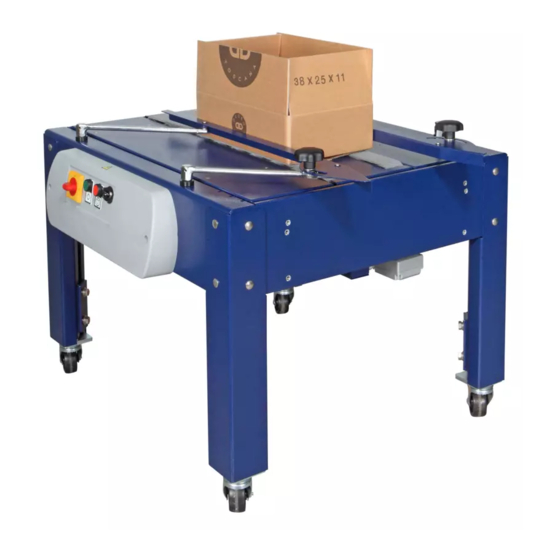
Chapter TEChNICAL INforMATIoN 3.1. machIne General descrIpTIon – INDEX 50/65 is a feeder-spacer for carton boxes. The machine is composed of a frame on which the boxes transit by means of two motorised conveyor belts. The machine must be installed upstream a taping machine and downstream a roller conveyor. - Page 21 Chapter 3 TEChNICAL INforMATIoN The illustration gives some examples of machine models. main parts a) Base B) Transport unit: The two motorised conveyors move the box on the roller unit. c) adjustable guides d) electric panel According to the different operating requirements, this machine can be supplied in different models and configurations.
-
Page 22: Description Of The Operation Cycle
Chapter 3 TEChNICAL INforMATIoN 3.2. descrIpTIon of The operaTIon cycle 1. The box, arriving from the roller unit, moves on the machine using the conveyor belt and when it exits the machine it triggers the micro-switch that the stops the conveyor. -
Page 23: Safety Device Descriptions
Chapter 3 TeChniCal informaTion 3.3. Safety device deScriptionS The figure shows the positioning of the devices on board of the machine. china. a) Main electrical knife switch (with padlock): to activate and deactivate the power supply. It comes with a padlock to prevent unauthorised personnel from activating the power supply. -
Page 24: Description Of Accessories On Request
Chapter 3 TeChniCal informaTion 3.5. Description of accessories on request To enhance the performance and to increase the versatility of the machine, the manufacturer furnishes the accessories listed below. a) Casters with brake (set of 4 wheels). B) infeed roller conveyor l=500 mm. 15C011011 3.6. - Page 25 Chapter 3 TeChniCal informaTion Table 3.2.: Box dimensions. Machine model Description INDEX 50 INDEX 65 14C305013 L min. 150 mm L max. ∞ W min. 110 mm W max. 500 mm 650 mm H min. with table in standard See taping machine downstream position H max with table in standard See taping machine downstream...
-
Page 26: Noise Level
Chapter 3 TEChNICAL INforMATIoN 3.7. noIse leVel The noise levels were measured in compliance with the: – ISo 4871 – ISo 11201 Table 3.4.: Noise level Description dB (A) dBw (A) mW (A) dB (A) Empty operation 47.0 63.0 0.00 52.7 functioning in working conditions 67.9... -
Page 27: Information On Handling And Installation Operations
Chapter InformaTIon on hanDlIng anD InSTallaTIon oPeraTIonS 4.1. Recommendations foR handling and loading – Before performing any operation, the authorised operator must make sure that he/she understood the “instructions for use”. – Carefully read the “Instructions for use” specified in the manual and those applied directly to the machine and/or the package. -
Page 28: Transport And Handling
Chapter 4 InformatIon on handlIng and InstallatIon operatIons 4.3. TransporT and handling transport, also according to the destination, can be performed by different vehicles. the diagram represents the most popular solutions. during transport, with the purpose to Transport vehicles avoid sudden movements, adequately anchor the machinery to the means of transportation. -
Page 29: Machine Installation
Chapter 4 INforMATIoN oN hANDLINg AND INSTALLATIoN oPErATIoNS 4.4. machIne InsTallaTIon following are the steps to be taken to install dismantled parts. Proceed as indicated 1. Lift the machine (See 4.3. “transport and handling”). 2. If the machine is equipped with swivel wheels (f), screw them onto the feet. -
Page 30: Installation Of Consent Switch
Chapter 4 INforMATIoN oN hANDLINg AND INSTALLATIoN oPErATIoNS 6. If machine is supplied with casters, block them. 4.5. InsTallaTIon of consenT sWITch Install switch (a) on taping machine. The triggered micro-switch stops the conveyor belts of the Index and when released it starts the timer. -
Page 31: Recommendations For Connections
Chapter 4 INforMATIoN oN hANDLINg AND INSTALLATIoN oPErATIoNS 4.6. recommendaTIons for connecTIons Important connections should be performed following the manufacturer’s indications in the enclosed diagrams. personnel authorised to perform this operation must possess technical skills, abilities and have acquired certified experience in the specific field and must perform connections professionally, taking into account all the regulative and legislative requirements. -
Page 32: Information On Adjustments
Chapter INforMATIoN oN ADjUSTMENTS 5.1. recommendaTIons for adjusTmenTs – Before performing any operation, the authorised operator must make sure that he/she understood the “Instructions for use”. – Before carrying out any intervention, activate all the safety de- vices provided, stop the machine and assess if any residual energy is still present. -
Page 33: Conveyor Belt Adjustment
Chapter 5 INforMATIoN oN ADjUSTMENTS 5.2. conVeyor BelT adjusTmenT Proceed as indicated: 1. Deactivate the main electric switch to put the machine in safety conditions. 2. remove transmission cover (a). 3. Loosen nut (c). 4. remove caps (B). 5. Act on screw (d) to adjust belt tension (e). Important To check tension, attain to what indicated in the figure. -
Page 34: Adjustment Of Self-Centering Guides Driving Chain
Chapter 5 INforMATIoN oN ADjUSTMENTS 5.3. adjusTmenT of self-cenTerInG GuIdes drIVInG chaIn Proceed as indicated. 1. Deactivate the main electric switch to put the machine in safety conditions. 2. operate the counter nuts (e) and the nuts (f) to adjust the tension of chain (G). -
Page 35: About The Use
Chapter AboUT ThE USE 6.1. recommendaTIons for operaTIon and use – Before performing any operation, the operator must make sure that he/she understood the “Instructions for use”. – When using the machine for the first time, the operator must read the manual and identify the controls and simulate some operations, especially the start-up and shutdown. -
Page 36: Switching The Machine On And Off
Chapter 6 AboUT ThE USE 6.3. sWITchInG The machIne on and off Proceed as indicated. switching on 1. Turn the master switch (a) to I (on) to activate the power supply. switching off 2. Turn the master switch (a) in position 0 (off) to disable the power supply. -
Page 37: Emergency Stop And Restart
Chapter 6 AboUT ThE USE 6.5. emerGency sTop and resTarT Turn the main switch (a) to position 0. Machine operation stops immediately. After normalising operating conditions, turn the main switch (a) to 1 (on) to authorise the restarting of the machine. -
Page 38: Positioning Of Side Guides
Chapter 6 About the use 6.7. Positioning of side guides Proceed as indicated. 1. Loosen the knobs (Q) and widen the guides. 2. Position the boxes to be moved. 3. Adjust the position of guides (R) leaning the guides against the box. 4. -
Page 39: Maintenance Information
Chapter MAINTENANCE INforMATIoN 7.1. maInTenance InsTrucTIons ‒ a good maintenance will allow for a longer working life and constant compliance with the safety requirements. ‒ Before performing any operation, the authorised operator must make sure that he/she understood the “Instructions for use”. ‒... -
Page 40: Maintenance Period Table
Chapter 7 MAINTENANCE INforMATIoN 7.2. maInTenance perIod TaBle Important Keep the machinery in maximum efficiency condition and perform all the scheduled maintenance operations provided for by the manufacturer. proper maintenance will provide the best performance, a longer life span and constant compliance with safety requirements Table 7.1.: routine maintenance intervals Frequency Component Type of intervention Procedure... -
Page 41: Lubrication Point Diagram
Chapter 7 MAINTENANCE INforMATIoN 7.3. luBrIcaTIon poInT dIaGram The following diagram shows the main components and the frequency of the lubrication interventions. 200 h 15C011023 Symbol and Description Smear with grease. keep to the recommended lubrication frequency to get top machine performances and a longer operating life. -
Page 42: Lubricants Table
Chapter 7 MAINTENANCE INforMATIoN 7.4. luBrIcanTs TaBle Table 7.2.: Lubricant specifications. Type of lubricant Name Parts to be lubricated 23°C a 50°C - 320 CST a 40°C MELLANA oIL 320 IP SPArTAN EP 320 ESSo bLASIA 320 AgIP gear motor MobILgEAr 632 MobIL oMALA EP 320 ShELL ENErgoL gr-XP 320 bP... -
Page 43: Troubleshooting
Chapter TRoubLeShooTing 8.1. Troubles – causes – remedies The troubleshooting table lists the problems, the possible causes and solutions. Table 8.1.: List of problems. Problem Cause Remedy The box blocks during transit. Conveying belts worn out. Replace conveying belts. See 9.2. “conveyor belt replacement”. -
Page 44: Spare Parts Replacement Information
Chapter SPArE PArTS rEPLACEMENT INforMATIoN 9.1. recommendaTIons for replacInG parTs – Before performing any operation, the authorised operator must make sure that he/she understood the “Instructions for use”. – carry out the interventions with all the safety devices enabled and wear the dpI provided. –... -
Page 45: Replacement Of Conveyor Belt
Chapter 9 SPArE PArTS rEPLACEMENT INforMATIoN 9.2. replacemenT of conVeyor BelT Proceed as indicated. 1. Deactivate the main electrical knife to stop the machine under safe conditions 2. remove transmission cover (a). 3. Loosen nut (c). 4. remove caps (B). 5. -
Page 46: How To Replace The Self-Centering Guide Driving Chain
Chapter 9 SPArE PArTS rEPLACEMENT INforMATIoN 9.3. hoW To replace The self- cenTerInG GuIde drIVInG chaIn Proceed as indicated. 1. Deactivate the main electrical knife to stop the machine under safe conditions. 2. Unscrew the nuts (e - f) to loosen chains (G) completely. 3. -
Page 47: Replacing The Chain That Moves The Conveyor Belts
Chapter 9 SPArE PArTS rEPLACEMENT INforMATIoN 9.4. replacInG The chaIn ThaT moVes The conVeyor BelTs Proceed as indicated. 1. Deactivate the main electrical knife to stop the machine under safe conditions. 2. remove transmission cover (a). 3. remove link (c) and remove chain (B). 4. -
Page 48: List Of The Recommended Spare Parts
Chapter 9 SPArE PArTS rEPLACEMENT INforMATIoN 9.5. lIsT of The recommended spare parTs List of the spare parts of easy wear and of which it would be necessary to have available to avoid long operation stops of the machine. for ordering, contact your local Dealer and refer to the spare parts catalogue. -
Page 49: Enclosed Documentation
Chapter 10 ENCLoSED DoCUMENTATIoN 10.1. WarranTy condITIons roboPAC S.p.A. pledges, within the limits described herein, to replace or repair, at no charge, the parts that become defective during the 12 (twelve) months following the date indicated on the company’s shipping documents. - Page 50 Chapter 10 ENCLoSED DoCUMENTATIoN Page deliberately empty - 46 - English...
Need help?
Do you have a question about the Robopac INDEX 50 and is the answer not in the manual?
Questions and answers