Advertisement
Quick Links
Advertisement

Related Manuals for Heatmiser RC1-WTS


Summary of Contents for Heatmiser RC1-WTS
- Page 1 Heatmiser RC1-WTS Wireless Receiver Ref: RC1-WTS Rev: 1.0...
- Page 3 Contents Installa on Procedure Pairing Instruc ons LED’s Explained Diagrams...
- Page 4 Installa on Procedure The receiver is designed to be surface mounted. A back box of 35mm should have been sunk in the wall prior to installa on. Step 1 Carefully separate the front half of the receiver from the back plate by placing a small flat head terminal driver into the slots on the bo om face of the thermostat.
- Page 5 Step 5 Clip the receiver front onto the back plate. Pairing the Thermostat To pair the thermostat with the receiver, follow these steps; On the receiver; Press the Pairing bu on. The Communica on LED will come on On the thermostat; Press Prog Press Setup At the top of the LCD, you will see 01.
- Page 6 Use the Up/Down keys to enter the address Press Setup to Pair the thermostat. Pair Successful The Comms LED on the receiver should flash and then go out to indicate the pair is successful. The thermostat will then display the communica on icon.
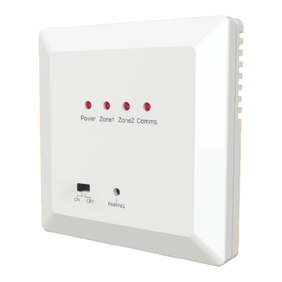
- Page 7 LED’s Explained There are 4 lights on the receiver. Power Zone 1 Zone 2 Comms On/Off Pairing Switch Bu on...
- Page 12 Support 01254 870303...
Need help?
Do you have a question about the RC1-WTS and is the answer not in the manual?
Questions and answers