Advertisement
Advertisement
Table of Contents

Related Manuals for Heatmiser RC1-W1


Summary of Contents for Heatmiser RC1-W1
- Page 1 Model: RC1-W Model: RC1-W...
- Page 2 Model: RC1-W Table of Contents Product Image Table of Contents Installation Procedure LED’s Explained Wiring Diagrams Notes 9-10 Wireless Receivers Wireless Receivers Model: RC1-W...
-
Page 3: Installation Procedure
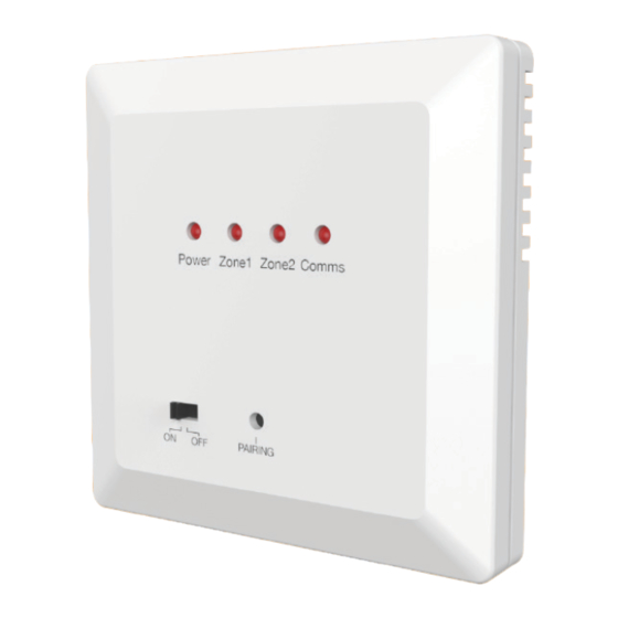
Installation Procedure Please read the instructions fully so you get the best from our product. This receiver is designed to be flush mounted and requires a back box of 35mm (minimum depth) to be sunk into the wall prior to installation. Step 1 Carefully separate the front half of the receiver from the back plate by placing a small flat head terminal driver into the slots on the bottom face of the receiver. - Page 4 Wiring Diagram - RC1-W LED Status Two Zone Heating System Two Zone Heating System There are 4 LED lights on the receiver. Heating Zone 1 Valve Each LED is labeled and will light up or flash during setup and operation. Please refer to your thermostats instructions for LED status information.
- Page 5 Wiring Diagram - RC1-W Wiring Diagram - RC1-W One Heating Zone & One Hot Water Zone System Combination Boiler System Heating Zone 1 Valve To Boiler P/L and S/L connections will vary To Boiler depending on the boiler model but S/L P/L Neutral S/L = Switched Live...
- Page 6 Wiring Diagram - RC1-W With Mid Position Valve Notes Cylinder Mid Position 230V Single Relay* Stat Valve ..................................Hot Water OFF Grey ..................................Hot Water ON Orange ..................................Heating ON White ....................................................................Neutral ..................................Live ..................................Supply In ..................................B1 A2 A1 85-230V AC ..................................
- Page 7 Heating Professionals: Request a copy of our product installation guide containing detailed technical specifications for our complete product range: www.heatmiser.com/guide Want More Information? Call our support team on: +44 (0)1254 669090 Or view technical specifications directly on our website: www.heatmiser.com...
Need help?
Do you have a question about the RC1-W1 and is the answer not in the manual?
Questions and answers