Table of Contents
Advertisement
Quick Links
Advertisement
Table of Contents

Summary of Contents for White Mini-Seis III Pro
- Page 1 MINI-SEIS III Pro™ OPERATING MANUAL...
-
Page 2: Table Of Contents
New Features ......................... 9 Connectors ........................9 Connecting a Sensor ......................9 Communication ....................... 10 Charging ......................... 10 The Keypad and Display ..................... 11 ON Key ..........................11 OFF key ........................... 11 ENTER Key ........................11 Mini-Seis III Pro™ Operating Manual Page 2... - Page 3 Mode Screen Functions (Waveform Mode) ................. 23 Rate ..........................23 Duration .......................... 23 Seismic Trigger ....................... 23 Acoustic Trigger ......................24 Trigger Level Considerations ..................24 Histogram Mode Functions ....................25 Rate ..........................25 Mini-Seis III Pro™ Operating Manual Page 3...
- Page 4 Heartbeat ........................32 Using a USB Thumb Drive ....................33 Field Use ..........................34 Transducer Coupling ....................... 34 Microphone ........................34 Preparing for Operation ...................... 35 Activating and Stabilization ..................... 35 Main Screen........................35 Mini-Seis III Pro™ Operating Manual Page 4...
- Page 5 HB ..........................44 HI ..........................45 RE ..........................45 RT..........................45 SM ..........................45 SSP ..........................45 SSP2 4 [unit] [range] [min] ................... 46 TA ..........................47 TS ..........................47 Limited Warranty ........................ 49 Mini-Seis III Pro™ Operating Manual Page 5...
-
Page 6: A Word Concerning This Manual
Data Analysis are the property of White Industrial Seismology, Inc. Introduction The Mini-Seis III Pro is an enhanced version of the Mini-Seis III and is designed to replace the Mini-Seis III. It features a 32 bit processor and 16 bit A/D. The Pro has over 3.5GB of memory and can store many hours or days of continuous waveform data and many months if not years of continuous histogram data. -
Page 7: Ranges And Resolutions
In waveform mode, at a sample rate of 1024 samples per second, the unit will operate for approximately 7 to 10 days with a full charge. With the Timer Mode set to an eight hour monitoring day, the continuous operating time can be extended to approximately one Mini-Seis III Pro™ Operating Manual Page 7... -
Page 8: Communication
Accessories and Software All required accessories are provided. The Seismograph Data Analysis software can be downloaded from the White website at www.whiteseis.com. Data Compression The Pro uses data compression to reduce the size of the downloaded files. The amount of compression will vary depending on the waveform characteristics and the selected resolution. -
Page 9: Non-Standard Sensors
Please check with White or your nearest Mini-Seis III Pro reseller for the availability of other ranges. TANDARD ENSORS The Pro does not support the direct display of data from non-standard sensors. However, the software can display and analyze data from non-standard sensors. -
Page 10: Communication
While we have tested many thumb drives, it is possible that not all USB thumb drives will function with the Pro. White recommends avoiding low priced generic cables in favor of known brands. Mini-Seis III USB cables are not compatible with the Pro and vice versa. -
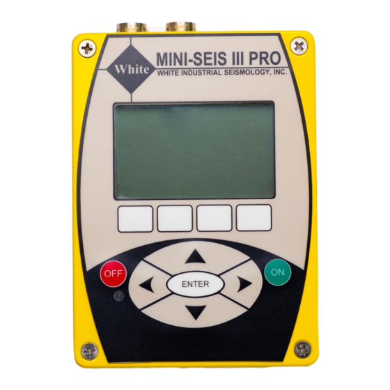
Page 11: The Keypad And Display
The Keypad and Display The Mini-Seis III Pro™ has various control keys that help to simplify operation. It also has an easy to read backlit graphics display. ON Key Pressing the ON key turns on the unit. The Pro can be activated without any sensors attached. -
Page 12: Instrument Screens (In Order As They Appear)
Instrument Screens (in order as they appear) Information Screen At power on the Mini-Seis III Pro will briefly display an information screen. The screen will show the model, serial number, firmware version and battery status. The display will be similar to the following:... - Page 13 This option should only be used by an authorized calibration facility. Back Go back to the previous soft key display. The Next soft key can be used to bypass stabilization. However, once the instrument is armed it may begin triggering. Mini-Seis III Pro™ Operating Manual Page 13...
-
Page 14: The Main Screen
Acoustic Trig:: 125 dB Next In this example, we can change the mode from Waveform when the trigger is disarmed. Pressing the right arrow key while Waveform is highlighted displays the Select Mode screen. Mini-Seis III Pro™ Operating Manual Page 14... -
Page 15: Event Screen
R: 0.802 16.78 T: 0.684 7.42 A: 125.0 33.7 Copy Back Histogram Events BAT: 6.5V JOB: 00003 08-28-2020 11:40:37 IPS/dB V: 0.237 9.85 R: 0.115 16.78 T: 0.213 7.42 A: 113.0 33.7 Back Copy Mini-Seis III Pro™ Operating Manual Page 15... - Page 16 This action does not calibrate the sensor, nor is it an indication of whether or not a sensor is in calibration. The calibration of a sensor can only be tested and adjusted with the proper equipment. Mini-Seis III Pro™ Operating Manual Page 16...
-
Page 17: Main Screen Functions
-Unit Options- -System Log Options- -Timer Setup- -Multi Triggering- Home Back PTIONS The Unit Options setup menu contains the following selections: Unit Options -File System- -Unit Setup- -Use Factory Defaults- -GPS- Home Back Mini-Seis III Pro™ Operating Manual Page 17... - Page 18 50 Hz to 10 kHz. The A weighted option should not be used for monitoring blast overpressure. The A weighting is non-ANSI certified Type 2 so ensure that this restriction is acceptable. Mini-Seis III Pro™ Operating Manual Page 18...
- Page 19 If using both linear and A weighting with separate microphones, it will be necessary to reprogram the acoustic channel each time a change is made. Contact White if help is needed. Air Units This field indicates the units that will be used to display acoustic data. Linear weighting options are dBL (linear decibels), Mb (millibars), PSI (pounds per square inch) and Pa (Pascals).
-
Page 20: System Log Options
If the On Timer is set to Enabled, no operating mode can be activated outside of the timer. The active operating mode will be started at the On time and stopped at the Off time. Timer Setup On Timer: Enabled Off Timer: Enabled Settings HR MIN Mini-Seis III Pro™ Operating Manual Page 20... -
Page 21: Multi Triggering
Main Screen Data Port The Data Port specifies what will be used for communication. The choices are RS232 and USB. The RS232 selection means that serial communication will be used which is the female Mini-Seis III Pro™ Operating Manual Page 21... -
Page 22: Main Screen Baud Rate
It is anticipated that USB will be used for direct connections and not RS232. Remote access using serial may necessitate using a lower baud rate if the signal quality is poor. Mini-Seis III Pro™ Operating Manual Page 22... -
Page 23: Mode Screen Functions (Waveform Mode)
The trigger resolution is based on the maximum range of the seismograph. The standard minimum trigger starts at 0.01 in/s (0.254 mm/s) and can be increased in steps of 0.005 ins (0.127 mm/s) based on a maximum range of 10.24 in/s (260 mm/s). Mini-Seis III Pro™ Operating Manual Page 23... -
Page 24: Acoustic Trigger
The ISEE Field Practice Guidelines for Blasting Seismographs 2017 Edition suggests 1.3 mm/s (0.05 in/s) seismic and 20 Pa (0.20 millibars or 120 dB). This document is available at www.isee.org. Mini-Seis III Pro™ Operating Manual Page 24... -
Page 25: Histogram Mode Functions
1. Do not set a timer. 2. Set the rate and period as desired. 3. Set the Interval to the number of hours desired. For illustration we will use 4. 4. Press the Activate soft key. Mini-Seis III Pro™ Operating Manual Page 25... -
Page 26: To Run An Interval Histogram Starting At A Specific Time
Note: Do not turn off power to the instrument while the histogram is active. Making the histogram inactive allows the firmware to write the proper summary entries. Failure to do this may result in a corrupted record. Mini-Seis III Pro™ Operating Manual Page 26... -
Page 27: Histogram/Waveform Mode Functions
This is the trigger threshold at which the unit will trigger from a ground vibration. To set the value, highlight the field and use the left or right arrow key. Holding the keys down will change the value at a faster rate. Mini-Seis III Pro™ Operating Manual Page 27... -
Page 28: Acoustic Trig
Note: Do not turn off power to the instrument while the histogram is active. Making the histogram inactive allows the firmware to write the proper summary entries. Failure to do this may result in a corrupted record. Mini-Seis III Pro™ Operating Manual Page 28... -
Page 29: Event Screen Functions
The cable uses the male DB9 connector on the seismograph. VENT PTIONS The Copy Event Options display gives us three copy options. All, Range or Date. The appearance of the display depends on the selected option. Mini-Seis III Pro™ Operating Manual Page 29... - Page 30 Use the Copy soft key to write the range of events specified to the thumb drive. Done Returns the display to the Event Screen Note: It is strongly advised to check the thumb drive to make sure the records were written correctly prior to erasing the seismograph’s memory. Mini-Seis III Pro™ Operating Manual Page 30...
-
Page 31: Channel, 8 Channel And Single Channel Configuration
Seismograph Data Analysis. However, it is recommended that only knowledgeable users employ CLI commands to change configurations. Should a configuration change be required, please contact White for the appropriate procedure to follow. Mini-Seis III Pro™ Operating Manual... -
Page 32: Automatic Reporting
The Command Terminal of the Seismograph Data Analysis software is used to program the seismograph for automatic reporting. Please refer to this software. Please note that the Pro is not supported by AutoReceive V2. Check with White for the version of AutoReceive that supports the Pro. -
Page 33: Using A Usb Thumb Drive
Using a USB Thumb Drive A very useful feature of the Mini-Seis III Pro is the ability to write records to a USB thumb drive at a very high rate. To do this a special cable is supplied. The cable has a female DB9 pin on one end and a USB slave receptor connector on the other end. -
Page 34: Field Use
The linear weighted microphone is used to record changes in overpressure. The measurements will be valid as long as the pressure around the element changes uniformly with the pressure change in the environment. Mini-Seis III Pro™ Operating Manual Page 34... -
Page 35: Preparing For Operation
After the transducer and microphone are installed, they can be connected to either one of the connectors on the Mini-Seis III Pro case. In the case of the 8 channel model, the outer most connectors are for channels 1-4, the inner most for channels 5-8. The sensors should be connected before turning on the power. -
Page 36: Example Steps For Monitoring Using Waveform Mode
8. If you left the Trigger field on the Main Screen on Disarmed, navigate to that screen and change the value to Armed. Otherwise, the unit will automatically arm itself after a brief period of inactivity, usually one to two minutes. Mini-Seis III Pro™ Operating Manual Page 36... -
Page 37: Example Steps For Monitoring Using Histogram Mode
8. If not using a timer, to begin monitoring, press the Activate soft key. 9. In not using a timer, when finished monitoring, return to the Histogram mode screen and press the Inactivt soft key. Turning off power without inactivating the histogram may corrupt the record. Mini-Seis III Pro™ Operating Manual Page 37... -
Page 38: Updating The Firmware
It will generally be advisable to apply the most recent version. Instructions for applying the update using Seismograph Data Analysis are available from the software help system. Applying an earlier software build can also be done, but there may be unexpected issues. Mini-Seis III Pro™ Operating Manual Page 38... -
Page 39: Cli Commands
If passed with no parameters and the current mode is 2 or 3, 2 = Fixed mode returns the current values of all parameters. 3 = Interval mode HH: 00–23 (required for fixed and interval modes) Mini-Seis III Pro™ Operating Manual Page 39... - Page 40 RI interface Get or set the interface used for remote reporting and interface: heartbeats. If passed with no parameters, returns the current 0 = RS-232 value. 1 = USB Reset the seismograph. none Mini-Seis III Pro™ Operating Manual Page 40...
- Page 41 Sensor-type 2 parameters affect channel 4 only. If sensor type 2 sensor-type specific. is selected, then channel 8 (if enabled) uses the SSP 0 settings. For air: 0: dBL 1: mb 2: Pa 3: PSI For seismic: 0: IPS 1: MMPS Mini-Seis III Pro™ Operating Manual Page 41...
- Page 42 HH: 00–23 MM: 00–59 Mini-Seis III Pro™ Operating Manual Page 42...
-
Page 43: Enhanced Descriptions
A weighted. The Pro supports non-ANSI certified Type 2 A weighting through the use of a logarithmic amplifier board. It will be best to use a separate microphone for A weighting versus that Mini-Seis III Pro™ Operating Manual Page 43... -
Page 44: Chen
CHEN The Mini-Seis III Pro is available in a 4 or 8 channel configuration. It will be configured at the factory based on the choice of 4 or 8 channel. An 8 channel unit can be configured as a 4 channel unit by issuing the CLI command CHEN 1. -
Page 45: Ssp
The [units] can be: With the exception of dBL, the range value should be in the units specified. If dBL, the range value should be in millibars. This is because the decibel is logarithmic. Mini-Seis III Pro™ Operating Manual Page 45... -
Page 46: Ssp2 4 [Unit] [Range] [Min]
It is recommended that Seismograph Data Analysis be used to deal with the presentation of single channel data. It has an advanced record feature that allows the user to custom specify the unit and range. Mini-Seis III Pro™ Operating Manual Page 46... - Page 47 8 channel unit the sensor can be 1 or 2. [channel] – Channel type. The value is 0 for acoustic or 1 for seismic. [tier] – Tier number. The value is 1 for tier 1 or 2 for tier 2. Mini-Seis III Pro™ Operating Manual Page 47...
- Page 48 2 for 0.5 ips. To determine the A/D count we use the last equation shown for the TS command. We are assuming a 10.24 ips range. ∗ 32768) + 32768 = 34368 10.24 TT 1 1 2 34368 is the command. Mini-Seis III Pro™ Operating Manual Page 48...
-
Page 49: Limited Warranty
This warranty is in lieu of all other warranties expressed or implied, and White Industrial Seismology, Inc. assumes no liability related to the use of its products other than that specified herein.