Advertisement
Quick Links
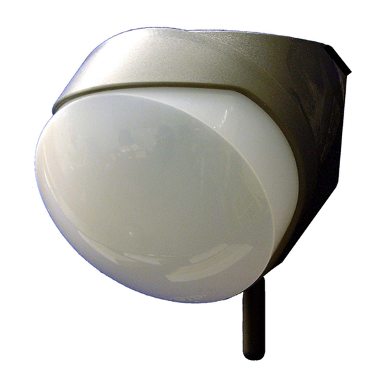
OPAL RFX
GJD018 35m External PIR
The wireless Opal RFX external passive infrared intruder
detector design to detect and transmit reliable event
based triggers to the weatherproof RFX-3 Receiver. These
combined units enable the simultaneous or individual
control of cameras, VCR's, DVR's and virtually all low-
voltage switching requirements.
The weatherproof receiver with front and rear tamper
output can be positioned in line of sight up to 150m away.
The active state of up to 3 Opal RFX PIR's is constantly
monitored. These signals are directed to their respective
volt free outputs and in addition there are a further eight
individual monitoring and information outputs.
The RFX-3 Receiver monitors the active state of up to
three Opal RFX passive infra red detectors.
The RFX-3 Receiver can be mounted externally or
internally. The transmission distance of 150m can be
obtained if the detectors are in true line of sight to the
receiver. When installing the RFX-3 Receiver internally, the
transmission distance of 150m will be reduced depending
on the thickness and type of material structure the radio
signals have to pass through or around.
It is advisable to conduct an RF continuity test when
mounting the receiver internally to ensure that the radio
signals can be received in the desired locations. (RF
continuity test page 3).
14
13
12
11
10
RF1
9
RF2
RF3
1
LN
12V
35mA
LO
GJD
A1
1
RFX-3
RECEIVER
A2
A3
2
S
RF1
RF2
3
RF3
CCTV
1
CCTV
2
CCTV
3
N/O
N/C
CCTV 1 2 3 T-20 +55C
FIG 1
8
WIRELESS TRANSMISSION
Each detector transmits radio signals to the receiver and
has over 16.7 million individual codes. The receiver only
responds to the transmitter that has been linked to a
channel to identify it.
The receiver can only analyse this information after the
individual code has been transferred via the secure wire
code learning link. This transfer is only required on the
initial setup, any subsequent changes to the detector
programming will be relayed by radio automatically to the
receiver. (programming chart - page 3).
FEATURES
1.
Secure wire code transfer connector
2.
Power supply input
3.
LO- output pulses every 5 seconds when any
batteries are low
4.
3 x 'A' -ve outputs which activate for -.4 seconds on
detection (24hour)
5.
'S' output - photocell controlled
6.
3 x RF- loss of active signal outputs. Activates 5
mins. after not receiving a signal from a registered
detector.
7.
3 x independent volt free CCTV contacts. Adjustable
0.4 to 60 seconds.
8.
Selection jumper - Normally open or normally closed
CCTV contacts
9.
3 x RF loss of signal LED indicators
10.
10. Reception - gives indication of the radio signal
being received.
(a) Flicker =normal
(b) On and off indicates conflict with other radio
equipment on the same frequency in close
proximity.
11.
3 x Channel buttons
For us in code transfer function only.
Plus detection indicator that light for the length of the CCTV
2
timer setting.
12.
Battery low indicator corresponding detection
3
indicator will also flash every 5 second when battery
is low (see 3).
4
13.
Tamper will activate/
(a) when cover removed or
5
(b) displacing from the mounting point
6
14.
Aerial
7
Advertisement

Related Manuals for GJD OPAL RFX GJD018


Summary of Contents for GJD OPAL RFX GJD018
- Page 1 OPAL RFX GJD018 35m External PIR The wireless Opal RFX external passive infrared intruder WIRELESS TRANSMISSION detector design to detect and transmit reliable event Each detector transmits radio signals to the receiver and based triggers to the weatherproof RFX-3 Receiver. These has over 16.7 million individual codes.
-
Page 2: Battery Installation
RFX-3 RECEIVER INSTALLATION 1. Apply the 12VDC to the receiver. The receiver has five cable inlets which have individual 2. Plug in the link wire from the first detector in to the moisture and insect blanking plates. There are three double receiver (see fig 4). - Page 3 (Seconds) Press 6 times to flash out your selected settings Press 7 times to reset to GJD factory settings Press 8 times and hold to start RF continuity test (see page 3) Press 9 times and hold to generate alternative random code...
-
Page 4: Testing Outputs
OPAL RFX INSTALLATION Floodlights also emit haze ripple. When installing During installation the electronics must be protected floodlights to provided movement activated lighting, against water, as trapped moister can effect or damage position the floodlights at the side or above the detector. A the unit. -
Page 5: Pet Immunity
MULTIBEAM LENS DATA The GJD multifunction lens fitted to the OPAL RFX detector produces 9 long range beams and 9 medium to short range curtain beams. Movement across the beams produces the best response and range, whilst movement towards the detector will be less responsive. - Page 6 Weight - 152g SIMPLIFIED EU DECLARATION OF CONFORMITY Dimensions 110h x 100w x 100 deep Hereby, GJD Manufacturing Ltd declares that the radio CERTIFICATIONS equipment type GJD017 RFX-3 Receiver is in compliance with Directive 2014/53/EU. The full text of the EU declaration of conformity is available at the following internet address: gjd.co.uk...
- Page 7 ENGINEER NOTES www.gjd.co.uk info@gjd.co.uk +44 (0) 1706 363 998 Unit 2 Birch Business Park, Whittle Lane, Heywood, Greater Manchester, OL10 2SX, UK...
Need help?
Do you have a question about the OPAL RFX GJD018 and is the answer not in the manual?
Questions and answers