
Related Manuals for ION FALCO


Summary of Contents for ION FALCO
- Page 1 30 AÑOS AL SERVICIO DE LA INDUSTRIA FALCO and FALCO Instrument User Manual V1.2R Register your instrument online to receive your extended Warranty. Unrivalled Gas Detection. ionscience.com...
- Page 2 FALCO Instrument User Manual V1.2R Register your instrument online for extended warranty Thank you for purchasing your Ion Science instrument. The standard warranty of your FALCO 1.2 VOC Monitor is for one year. To receive your extended warranty, you must register your instrument online within one month of purchase (terms and conditions apply.)
-
Page 3: Table Of Contents
FALCO Instrument User Manual V1.2R Contents Contents ............................3 Safety ............................6 Legal Notices Regarding the Safe Operation of Equipment ............... 6 Symbols ............................... 6 Warnings, Cautions and Information notifications ................6 Disposal ............................... 8 Certification FTZÚ ........................9 Declaration of Conformity ......................10 Statements .......................... - Page 4 FALCO Instrument User Manual V1.2R Sampling Tube Length ........................ 23 Removal of the Control Module....................23 To Remove the Control Module ....................23 Operating the FALCO ........................24 User Interface ...........................24 Status Light ............................24 Start-Up Routine ........................25 Logo Screen ............................25 Info screen 1 .............................25...
- Page 5 FALCO Instrument User Manual V1.2R Alarm 1..............................35 Alarm 2..............................36 Alarm Brightness........................36 Alarm Pulsing ..........................36 Relays ............................37 Relay 1 Options ..........................37 Relay 2 Options ..........................37 4 – 20 mA ..........................37 4 – 20 mA Enable/Disable.........................37 4 - 20mA Range..........................38 Modbus Address ........................
-
Page 6: Safety
• To the extent permitted by law, ION Science shall not be liable to any person or entity for any loss or damage which may arise from the use of this manual. - Page 7 The Falco must not be exposed to atmospheres known to have an adverse effect on Thermoplastic Elastomers or Polycarbonate. Outside the items covered in this manual, the Falco must be serviced in a Non- Hazardous environment and by ION Science Ltd authorised service centres only.
-
Page 8: Disposal
• Always adhere to local regulations and procedures when disposing of the equipment. • Ion Science Ltd offers a take back service. Please contact us for more information. RECYCLING Recycle all Packing. WEEE REGULATIONS Ensure that all waste electrical equipment is disposed of correctly. -
Page 9: Certification Ftzú
FALCO Instrument User Manual V1.2R Certification FTZÚ Unrivalled Gas Detection. ionscience.com Page 9 of 46... -
Page 10: Declaration Of Conformity
FALCO Instrument User Manual V1.2R Declaration of Conformity Unrivalled Gas Detection. ionscience.com Page 10 of 46... -
Page 11: Statements
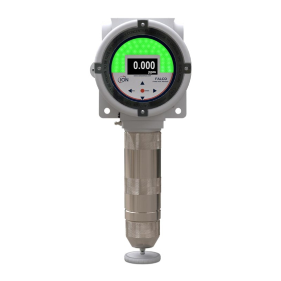
(VOCs) in the atmosphere. VOCs can be dangerous as they are poisonous to humans and there is a risk of explosion. VOCs are detectable using photo ionisation detection (PID) detector. The FALCO’s multi coloured LED status display screen can be seen from a distance of twenty metres in direct sunlight ensuring that personnel are alerted to hazards present. -
Page 12: Technical Specification
(LED). It also has a galvanically separated 4-20 mA current loop, Modbus (serial communication protocol) and two configurable switched contacts. For protection in explosive areas the FALCO’s Main Unit electronics are fitted in an ExD enclosure and the PID Sensor Head utilises intrinsically safe electronics. -
Page 13: Un-Packing
Specifications are based on isobutylene calibration at 20 °C and 1000 mBar. Un-Packing All equipment shipped by Ion Science Ltd is packed in containers with shock absorbing filling to protect them against physical damage. Remove the contents carefully and check them against the packing list. Report discrepancies between the contents and the packing list to Ion Science Ltd. -
Page 14: Rs485 Modbus Interface
FALCO Instrument User Manual V1.2R RS485 Modbus Interface The FALCO Modbus interface uses Modbus RTU • 9600 baud, 8 data bits, no parity, 1 stop bit. Register Register Name Function Code Data Type Range Address 3 - Read Holding Gas concentration 32-bit Float ±1.175494E-38 to ±3.402823E+38... -
Page 15: Installation Requirements
For further guidance please consult the relevant local standards or local occupational health representatives. INFORMATION • If the VOCs being detected are known to be lighter than air install the FALCO unit as high on the wall as is practical. •... -
Page 16: Installation
FALCO Instrument User Manual V1.2R Installation INFORMATION Before installing the FALCO unit thoroughly read the technical specification contained in this User Manual Preparation for Installation Before you install the FALCO, refer to the: • Instrument User Manual • Location Requirements •... -
Page 17: Installing The Housing Module
PID Housing Cover To install the FALCO as a complete assembly Use two M8 screws to install the FALCO as a complete unit (Main Unit and Sensor Housing together) on a solid, stable support. After you install the FALCO, unscrew and remove the Front Cover. Unbolt the three bolts holding the control module (4) from the ExD Housing Module (2). -
Page 18: After-Installation Test
Installation in Zones with Explosive Atmospheres The wiring diagram for the Falco is shown below, that covers in input power, MODBUS and Current Loop. There are four possible configurations for the 4 – 20 mA current loop depending on the installation site that are following section. -
Page 19: Configurations Of The 4 - 20 Ma Current Loop
All configurations are galvanically isolated from the 8 – 40 Vdc power supply used to power the Falco instrument. This DIP switch can be found near the ribbon cable and is labelled 4 - 20mA LOOP. Falco Current Loop Configuration 1 – active current loop, using internal power supply connected to the current source. Unrivalled Gas Detection. - Page 20 FALCO Instrument User Manual V1.2R Falco Current Loop configuration 2 – passive current loop, externally powered current source. When using this configuration ensure that the current loop circuit has voltage is between 8.5 V and 12 V, at Loop + after the resistances of the line have been taken into consideration.
- Page 21 FALCO Instrument User Manual V1.2R Falco Current Loop Configuration 3 – passive current loop, externally powered current source When using this configuration ensure that the current loop circuit has voltage is between 8.5 V and 12 V, at Loop + after the resistances of the line have been taken into consideration.
- Page 22 FALCO Instrument User Manual V1.2R Falco Current Loop Configuration 4 – active current loop, using internal power supply connected to the current source. Unrivalled Gas Detection. ionscience.com Page 22 of 46...
-
Page 23: Hydrophobic Filter
Hydrophobic Filter It is very important to prevent the ingress of water and moisture into the Falco as this can cause damage to the PID sensor and electronic circuits. Please ensure that before running Falco you have attached a hydrophobic filter to the instrument. -
Page 24: Operating The Falco
Status Light Yellow Displayed during start-up only, when power is first applied. Green Indicates that FALCO is operating correctly. Also displayed during the start-up routine. Amber Flashing amber indicates Alarm 1 has been triggered i.e. the measured level of VOC is above the alarm threshold. -
Page 25: Start-Up Routine
When power is applied, the Status Light goes yellow. The FALCO will then display the following screens, in this order: Logo Screen After the power is turned on, the FALCO displays the 'Ion Science' logo for 3 seconds and the status light is green. Info screen 1 Info screen 1 then appears for 3 seconds. -
Page 26: Normal Running Mode Screen
FALCO Instrument User Manual V1.2R INFORMATION After switch-on the instrument should be allowed to acclimatise for 30 minutes before working in its ‘Normal running mode’. The warm-up time can be skipped by pressing the Enter key. Normal Running Mode Screen The screen then appears continuously and shows the PID reading and units. -
Page 27: Lock Screen
FALCO Instrument User Manual V1.2R To access the settings menus, press the Right key from the Normal Running Mode screen. If a passcode has been set, the Lock screen will be displayed. Otherwise, the i1 menu will be displayed. Lock Screen The Lock screen is displayed if a password number has been specified (see menu i6). -
Page 28: Menu I1
MiniPID is off, indicates the MiniPID is on. From here you can also put the Falco into test mode. This means the Falco will simulate its output behaviours. To configure the Falco to display a fixed output level, select . -
Page 29: Menu I3
FALCO Instrument User Manual V1.2R Menu i3 Measurement Cycle: This allows you to change the time between updating outputs. Relay 1 output: The instrument has two relay outputs, both of which can be triggered by a condition selected by the user. The condition that triggers Relay 1 is selected via the Relay 1 output option. -
Page 30: Menu I6
FALCO Instrument User Manual V1.2R 20 mA range: Used to set the 20 mA range of the instrument. 4 - 20 mA fault level: Used to set whether the fault signal is <4 mA or > 20mA. Menu i6 Modbus address – Used to select a Modbus slave address. -
Page 31: Pump Operation
The calibration options are accessed from Menu i1 INFORMATION 0 – 10 and 0 – 50 ppm Falco require 2 point calibration (Zero and Span 1). 0 – 1000 and 0 – 3000 ppm Falco require 3 point calibration (Zero, Span 1 and Span 2). -
Page 32: Span 1
FALCO Instrument User Manual V1.2R cannot be confirmed zero air should be used. If using a cylinder attach the tubing between the Falco and the gas regulator. 2) Enter zero cal mode by moving the cursor to the zero cal icon and then press the Enter key. -
Page 33: Span 2
VOC’s response factor. If a response factor is applied the concentration displayed on the Falco will represent the concentration of the VOC. For example, if the RF is 00.50, and 100ppm is detected based on an isobutylene calibration: 100 ppm x 00.50 = 50 ppm is the value displayed... -
Page 34: Detection Units
FALCO Instrument User Manual V1.2R The default setting for the response factor is 1. To set a response factor move the cursor to the response factor icon and press the Enter key. A cursor is displayed under the first digit of the value. Press the Up or Down key to change it. -
Page 35: Measurement Cycle
The alarm levels are set in menu i2 The Falco has 2 alarms levels, 1 and 2. When alarm level 1 is reached the status bar will go amber and Alarm 2 is reached the status bar will go red. -
Page 36: Alarm 2
FALCO Instrument User Manual V1.2R Alarm 2 Used to set the ppm level at which Alarm 2 (red) is triggered. When accessed, the screen displays the current level. Set the Alarm 2 level in the same way as described for Alarm 1 above. -
Page 37: Relays
FALCO Instrument User Manual V1.2R Press the Esc key to return to the i3 menu without saving the change to the setting. Relays Relay options are accessed from menu i3 Relay 1 Options Used to specify which of 4 conditions will trigger the Relay 1 output. Each is represented by a symbol, as described below. -
Page 38: 20Ma Range
FALCO Instrument User Manual V1.2R 4 - 20mA Range The lower limit of the 4 mA to 20 mA output range, mapped to 4 mA, is 0 ppm. This option is used to set the upper limit, mapped to 20 mA. -
Page 39: Password Lock
FALCO Instrument User Manual V1.2R The power supplied to the MiniPID sensor is not dangerous to the user by either the risk of electrocution or cause a threat of an explosion in a hazardous environment. It is however good practice to remove local power to circuitry when servicing to avoid possible damage by short circuit. -
Page 40: Servicing
Part Number Sensor Cover 873206 O-Ring holder 873211 A-873227 Replacement O-Ring kit MiniPID 2 Falco White - MP6SM6FWXU2 MiniPID 2 Falco Orange - MP6SM6FOXU2 MiniPID MiniPID2 Falco TAC - MP6SXLFTXU2 Pump Housing O-Ring Pump Housing O-Ring A-873228 Pump Replacement Kit LA4SFL3.2... -
Page 41: Cleaning The Minipid
FALCO Instrument User Manual V1.2R Cleaning the MiniPID FALCO has been designed to ensure servicing is quick and easy: 1. Before servicing FALCO, set the device to Servicing Mode. 2. Unscrew the Sensor Cover (1) to access the MiniPID (4) located in the Sensor Housing. -
Page 42: Use Of Pid Lamp Cleaning Kit A-31063
Irreparable damage will be caused by forcing the MiniPID (4) into the Sensor Housing if not correctly aligned. INFORMATION Always calibrate the FALCO after servicing is carried out. Use of PID Lamp Cleaning Kit A-31063 The container of cleaning compound contains Aluminium Oxide as a very fine power (CAS Number 1344-28-1). -
Page 43: Fault Conditions
FALCO Instrument User Manual V1.2R Fault Conditions The FALCO is equipped with a number of diagnostics to ensure instrument faults are detected and communicated. The table gives a fuller description of each fault and lists some possible causes and corrective actions you can try. - Page 44 The analogue to digital converter has Contact Service Centre. stopped working. Make sure the Sensor Cover is screwed If error 3 occurs, the Falco’s lamp hasn’t on correctly.. Replace lamp if error struck. persists. Check the sample line for blockages. Also...
-
Page 45: Manual Log
Disclaimer: Information in this [manual, document…] is subject to change without notice and does not represent a commitment on the part of Ion Science. No claims, promises or guarantees are made about the accuracy, completeness, or adequacy of the information contained herein. -
Page 46: Ion Science Contact Details
FALCO Instrument User Manual V1.2R ON Science Contact Details UK and Head Office USA Office India Office ION Science Ltd ION Science Inc ION Science India The Hive, Fowlmere 4153 Bluebonnet Drive #1-90/B/B/3/1, Charmy Cambridge Stafford Vittal Rao Nagar SG8 7SL...
Need help?
Do you have a question about the FALCO and is the answer not in the manual?
Questions and answers