
Subscribe to Our Youtube Channel
Related Manuals for ION TVOC 2


Summary of Contents for ION TVOC 2
- Page 1 For Sales & Service Contact 2650 E. 40th Ave. • Denver, CO 80205 Phone 303-320-4764 • Fax 303-322-7242 1-800-833-7958 www.geotechenv.com TVOC 2 Instrument User Manual V1.1 Unrivalled Gas Detection. ionscience.com...
- Page 2 Thank you for purchasing your Ion Science instrument. The standard warranty of your instrument can be extended to up to five years on PhoCheck Tiger and two years on other Ion Science instruments. To receive your extended warranty, you must register your instrument online within one month of purchase ( terms and conditions apply.)
-
Page 3: Eu Declaration Of Conformity
Potentially Explosive Atmospheres – Application of Quality Systems Ion Science Ltd has sole responsibility, on the date this product accompanied by this declaration is placed on the market, the product conforms to all technical and regulatory requirements of the above listed directives. -
Page 4: Table Of Contents
Legal Notice ................................5 Introduction to TVOC 2 ............................... 6 Packing list .................................. 8 Standard TVOC 2 instrument ............................ 8 TVOC 2 Accessory Kit (A-900214) ..........................8 TVOC 2 Set-up ................................9 Selector Pins ................................9 Installation ................................11 Location ................................. 11 Cable and gland requirements.......................... -
Page 5: Statements
"as is" and without any representation, term, condition or warranty of any kind, either expressed or implied. To the extent permitted by law, Ion Science shall not be liable to any person or entity for any loss or damage which may arise from the use of this manual. -
Page 6: Introduction To Tvoc 2
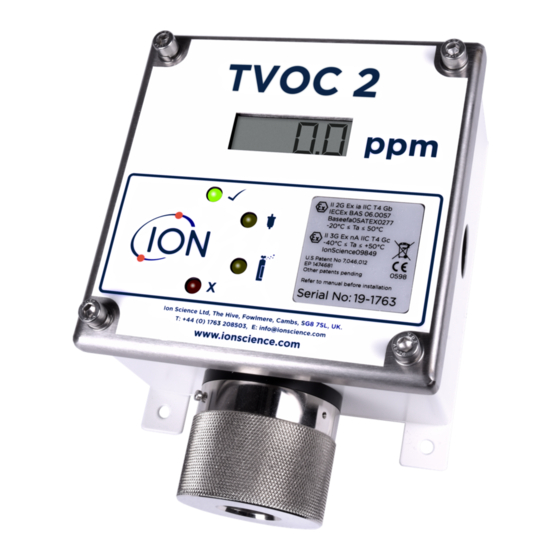
Units TVOC 2 gives a continuous 4-20 mA output which can be integrated into a DCS control system to give an indication of VOC levels in the operating environment. Note the 4-20 mA output must be externally powered with 8-35 V. - Page 7 TVOC 2 Intrinsically safe certificate for further details. The TVOC 2 safety rating permits its deployment in all hazardous areas of the quoted (or less demanding) rating. For detail please refer to the marking on your instrument (found on the front main label). Units are manufactured with two protection concepts applied by separate certifications.
-
Page 8: Packing List
Contents should be carefully removed and checked against the packing list. Any discrepancies between the contents and the packing list must be reported to Ion Science Ltd within ten days of receipt of shipment. Ion Science cannot be held responsible for shortages not reported with in the period. -
Page 9: Tvoc 2 Set-Up
TVOC 2 Set-up Selector Pins TVOC 2 has a number of settings that can be selected by the user via a row of four selector pins mounted on the reverse side of the main PCB. Diagram 2 shows the location of the functional selector pins labelled - A, B, C &... - Page 10 • TVOC 2 only reads the selector pin settings when power is connected. • Always ensure power is disconnected from TVOC 2 before changing setting or carrying out maintenance. • Never place selector pins on the programming port connector. •...
-
Page 11: Installation
• If possible, mount TVOC 2 near the ceiling to target VOC gases that are lighter than air or just above floor level to detect VOC gases that are heavier than air. •... -
Page 12: Dimensions For Mounting
Ion Science Ltd Installation Dimensions for mounting Diagram 5 NOTE: The TVOC 2 case can be used as a template when marking out fixing holes but do not drill through the fixing holes. Installation Power requirements Non-Intrinsically Safe Operation applications: Input power 5-28 Vdc. - Page 13 TVOC 2 MANUAL Ion Science Ltd 4 Wire System (Non-IS) Diagram 6 3 Wire System (Non-IS) Diagram 7 Unrivalled Gas Detection. ionscience.com Page 13 of 32...
- Page 14 TVOC 2 fuses may not be replaced in the field. • If a fuse is blown TVOC 2 will require inspection by Ion Science Ltd or an Ion Science Approved Service Centre before it is used in an IS application.
-
Page 15: Initial Calibration
TVOC 2 is calibrated at Ion Science before dispatch using 100 ppm Isobutylene. However, if you wish to calibrate your TVOC 2 after installation, Ion Science recommends the unit is left to run on its chosen settings (see ‘TVOC 2 Set-up Section’) for 24 hours before an initial calibration is carried out, to allow the instrument to stabilise. -
Page 16: Operation
Ion Science Ltd Operation Start-Up After electrical power is connected, TVOC 2 runs through a ‘Start-up’ routine, which lasts for approximately 1 minute. During this ‘Start-up’ routine TVOC 2 demonstrates the following characteristics: • The LCD screen displays the software version number •... -
Page 17: Selector Pins
Selector pins TVOC 2 has a range of options that are selected via the selector pins on the back of the main PCB (please see the ‘TVOC 2 Set-up’ Section). The options are shown below with the defaults highlighted in bold: 1-1000 ppm 0.01 –... -
Page 18: Calibration Routine
Calibration Calibration routine Ion Science recommends calibrating TVOC 2 after any maintenance or lamp cleaning is carried out and on a 3 monthly basis to ensure TVOC 2 is working to specification. NOTE: Please read this entire calibration procedure before attempting a calibration. -
Page 19: Setting The Span Gas Concentration
An acceptable ZERO calibration level will result in the illumination of the ‘STATUS LED’. An unacceptable ZERO calibration level will result in the illumination of the ‘FAULT LED’. Should this occur the TVOC 2 will not proceed to the gas tolerance setting and return to normal operation the previous calibration levels will be used. - Page 20 Now place the magnet over the logo to return to normal monitoring routine. The green ‘STATUS LED’ will begin flashing as TVOC 2 starts. IMPORTANT: Unacceptable calibration levels will not be adopted; the instrument will default to the previously stored acceptable calibration.
-
Page 21: Maintenance
TVOC 2 MANUAL Ion Science Ltd Maintenance Cleaning / replacing the lamp TVOC 2 has been designed to ensure servicing is quick and easy: Before servicing TVOC 2, disconnect the electrical power supply. Remove the locking screw from the metal sensor cap using the... -
Page 22: Inspecting The Minipid Stack
TVOC 2 MANUAL Ion Science Ltd Maintenance The electrode stack and PID lamp can then be removed using the Electrode Stack Removal tool (846216). Warning: Electrode Only use the electrode stack removal stack tool. Any other tools (for example screwdrivers) may damage your... - Page 23 Caution: The lamp cleaning kit contains alumina (CAS Number 1344-28-1) as a very fine powder. Cleaning should be undertaken in a well-ventilated area. A full material safety data sheet MSDS is available on request from Ion Science Ltd. Key safety issues are identified below:...
-
Page 24: Assembly Of Minipid Electrode Stack, Lamp And Body
(IS) or not. For IS or Zone 2 applications the unit must be inspected and have the fuse replaced by Ion Science Ltd or an Ion Science Approved Service Centre. The intrinsically safe rating is not maintained if the fuse is simply replaced. -
Page 25: System Recommendations
Gas sample systems It is sometimes necessary to pump or draw a gas sample past the TVOC 2. For this a “Flow Adaptor " can be fitted. The flow adaptor has an inlet and an outlet port so that gas may be pushed or drawn across the sensor. See Diagram 22 above. - Page 26 2. The pressure difference of a pumped system relative to atmosphere should be minimised to avoid the effects of gas law. 3. The maximum pressure that can be applied to the TVOC 2 sensor housing is 300 mbar. However, this is not a recommended working pressure. Ideally working pressure should be +/- 30 mbar relative to ambient pressure.
-
Page 27: Instrument Warranty And Service
Service Ion Science is pleased to offer a number of service options on our TVOC 2 product range that allow you to choose the instrument cover that best suits your needs. At Ion Science we recommend that all of our gas detection instruments be returned for service and factory calibration once every 12 months. -
Page 28: Diagnostics
TVOC 2 MANUAL Ion Science Ltd Diagnostics Below are two conditions your TVOC 2 can be in when it is working correctly: Diagram 25 The conditions shown below are of the instrument in an error state with potential checks/cures for these faults: F1 Error If an F1 error occurs when the instrument is first switched on there may not be an issue. -
Page 29: F3 Error
PCB. If not push it fully home. F4 error The F4 error occurs when an incorrect selector pin setting is used, see TVOC 2 Set-up. Set a valid selector pin configuration and restart the unit. - Page 30 TVOC 2 Accessory Kit Calibration magnet, Calibration adaptor, Calibration connector, Zero gas aspirator, Carbon filter, 2 x Allen keys A-900214 Flow adaptor (TVOC 2 only) Replaces the standard Sensor Cap 900209 PID Lamp cleaning kit Alumina powder and cotton buds...
-
Page 31: Technical Specifications
7 Segment, 4 Digit LCD. 4 Colour LED’s Response Sensor T90 < 10 seconds TVOC 2 output update: 1 second Accuracy 0 to 100 ppm: +/- 5% or +/- 1 ppm (whichever is greater) 100 to 1000 ppm: +/- 10% Linearity 0 to 1000ppm >75%... -
Page 32: Manual Log
Manual log Manual Version Amendment Date updated Instrument PC Software Firmware TVOC 2 Manual New document for TVOC 2 04/07/19 V1.01 instrument based on V4.7 of the original TVOC manual TVOC 2 Manual Updated diagrams and 7/10/19 V1.01 V1.1 Accuracy specification.
Need help?
Do you have a question about the TVOC 2 and is the answer not in the manual?
Questions and answers