Table of Contents
Advertisement
Quick Links
Advertisement
Table of Contents

Related Manuals for Beltrame S2006


Summary of Contents for Beltrame S2006
-
Page 2: Table Of Contents
Index Index ............................2 Important Notice .......................... 4 Safety instructions ......................5 General ..........................5 Safety Instructions ........................6 Product description ......................7 Preface ........................... 7 Area of application ........................8 Hardware ..........................9 2.3.1 Control elements and interfaces ................10 2.3.2 Device connections: power and high voltage ............ - Page 3 Operations to be done while the machine is off ..............61 Maintenance and Breakdown ..................62 Maintenance ......................... 62 Problem Solving ........................62 General data ........................64 S2006 up to 15A........................65 S2006 up to 25A........................66 S2006 up to 40A........................67 3/67...
-
Page 4: Important Notice
Important Notice Our experience has shown that, if the information and recommendations contained in this Operating Instructions are observed, the best possible reliability of our products is assured. The data contained herein purports solely to describe the product and is not a warranty of performance or characteristics. -
Page 5: Safety Instructions
It is the owner’s responsibility to ensure that each person involved in the installation and commissioning of the S2006 has received the appropriate training or instructions and has thoroughly read and clearly understood the safety instructions in this chapter. -
Page 6: Safety Instructions
1.2 Safety Instructions The safety instructions always appear at the beginning of each chapter and/or precede any instruction in the context where a potentially dangerous situation may appear. The safety instructions are divided into five categories and emphasized by the use of the following layout and safety signs: DANGER! This symbol indicates an imminent danger resulting from mechanical forces or high voltage. -
Page 7: Product Description
RODUCT DESCRIPTION 2.1 Preface From a consolidated operating experience in the energy sector Beltrame has created a device of high performance: the S2006 voltage regulator. S2006 is an automatic voltage regulator of the latest design for synchronous generators and synchronous motors. -
Page 8: Area Of Application
2.2 Area of application This advanced-design automatic voltage regulator is used for the excitation of indirectly excited synchronous machines. This unit is only suitable for this one area of application. The regulator can also be switched over to function as a reactive power-, power factor- or field current regulator. SM = Synchronous Machine E = Exciter PMG = Permanent-Magnet-Generator... -
Page 9: Hardware
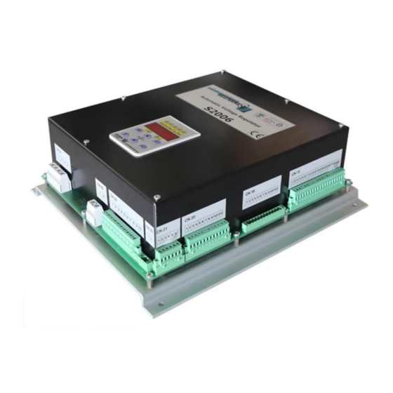
The operating keys and the display are located on the unit cover. Installation: The site of installation must be dry and free of dust. Mounting: The S2006 is designed for wall mounting. For optimal cooling is to keep free a minimum distance of 100mm all around the unit. Connection diagram: 9/67... -
Page 10: Control Elements And Interfaces
Parameter setting Display of important measuring values. Interface with PC Parameter setting and also optimization is possible using the user-friendly software S2006 Configurator for Microsoft Windows. Connection cable, standard USB with A-B connectors Configuration of inputs and outputs ... - Page 11 Terminal blocks Overview of the device connections 11/67...
- Page 12 CN1 – Communication USB (type B) CN 20 – Digital inputs V USB Digital input 10 Digital input 9 Digital input 8 GND USB Digital input 7 CN2 – Communication CANBUS Digital input 6 Digital input 5 CAN H Digital input 4 CAN H Digital input 3 CAN L...
-
Page 13: Device Connections: Power And High Voltage
2.3.2 Device connections: power and high voltage Terminal designation Signal Specifications Auxiliary supply (optional) AC input voltage 20 to 265 Vrms 50÷60 Hz DC input voltage 20 to 400 Vdc Power electronics supply input voltage Two models are available according three-phase to the maximum supply voltage: ... -
Page 14: Device Connections: Control Signals And Interfaces
2.3.3 Device connections: control signals and interfaces Terminal designation Signal Specifications Connection with internal supply Digital inputs 16 digital inputs connection with external supply opto-isolated 12-24V / 2,5mA programmable function 14/67... - Page 15 Terminal designation Signal Specifications Digital outputs 16 digital outputs relay, CO voltage-free contact 6A @ 250Vac 6A @ 30Vdc 0.2A @ 110Vdc 0.1A @ 220Vdc programmable function 15/67...
- Page 16 Terminal designation Signal Specifications Analog inputs 2 analog inputs opto-isolated differential input 0÷20mA / -10÷10V by software setting programmable function Analog output 2 analog outputs opto-isolated 4÷20mA maximum voltage 20V Load 47Ω ≤ Rc ≤ 470Ω Watchdog 1 digital output ...
- Page 17 Terminal designation Signal Specifications 1 RS485 opto-isolated half duplex multidrop, max 128 devices selectable termination Modbus proprietary protocols 1 CAN opto-isolated selectable termination CAN open and proprietary protocols galvanic isolation 2 Ethernet ...
-
Page 18: Operator Interface
3. O PERATOR INTERFACE In this following charter are described the operations of management parameter, using programming keyboard. 3.1 Control keyboard and signaling The modifications operated on the values of the parameters, also entering in action immediately, are not stored in way automatic, but require a specific action of storage that is obtained by means of the command “C.000”... -
Page 19: Navigating The Menus
(yellow Led): the function is freely programmable by parameter (default = calibrator at maximum) 3.2 Navigating the menus When the S2006 is power on, the display automatically shows parameter d.000 (Field current) in the Display menu. 19/67... - Page 20 Example: how to change the Iecc reference Example: how to save the parameters after the change 20/67...
-
Page 21: Display
3.3 Display 3.3.1 Field Parameter Description Notes d.000 Field current expressed in % of the excitation rated current (P.000) d.001 Field current reference expressed in % of the excitation rated current (P.000) d.005 Ripple level of the field current in % of the excitation rated current (P.000) d.010 Field voltage expressed in % of the excitation rated voltage... -
Page 22: Actual Regulation
3.3.4 Actual regulation Parameter Description Notes d.300 Control status Fault Stop PWM control FVR control FCR control Wait frequency Ramp AVR control PF/VAR control d.301 Control mode As P.300 d.302 Reference d.303 Feedback d.304 Error d.310 Proportional plus derivative gain d.311 Integral gain d.312... -
Page 23: Fieldbus
d.433 Analog input 2 monitor (local) d.434 Analog input 2 monitor (remote) d.440 Analog output 1 monitor (filtered) d.441 Analog output 1 monitor (conditioned) d.442 Analog output 1 monitor (raw) d.450 Analog output 2 monitor (filtered) d.451 Analog output 2 monitor (conditioned) d.452 Analog output 2 monitor (raw) 3.3.6 Fieldbus... -
Page 24: Exciter
d.856 Run time L d.982 d.857 Run time H d.983 d.858 Field Current d.000 d.859 Field Voltage d.010 d.860 Generator Voltage L1-L2 d.100 d.861 Generator Freq. Out d.104 d.862 Generator Current d.110 d.863 Generator Power Factor d.111 d.864 Control Status d.300 d.865 Control Mode... -
Page 25: Configuration
4. C ONFIGURATION 4.1 Inputs and outputs 4.1.1 Digital inputs The voltage regulator S2006 has 16 digital inputs. Parameter Input Default I.000 RUN (NO) I.001 GRID PAR SW (NO) I.002 PF REF2 (NO) I.003 SET RAISE (NO) I.004 SET LOWER (NO) I.005... -
Page 26: Enabling Virtual Digital Inputs
4.1.2 Enabling virtual digital inputs Through a "virtual setting" via serial line or fieldbus, it is possible to use all the functions available on the digital inputs. The setting can be carried out in such configurations, where the digital commands are a mix of "virtual" and terminals. -
Page 27: Digital Outputs
4.1.3 Digital outputs The voltage regulator S2006 has 16 digital outputs. Parameter Output Default I.100 Parallel CB (NO) I.101 Q = 0 (NO) I.102 Calibrator max (NO) I.103 Calibrator min (NO) I.104 Manual mode (NO) I.105 Fault (NO) I.106 PF 2nd reference (NO) I.107... -
Page 28: Enabling Virtual Digital Outputs
4.1.4 Enabling virtual digital outputs Through a "virtual setting" via serial line or fieldbus, it is possible to use all the functions available on the digital outputs. The setting can be carried out in such configurations, where the outputs are a mix of "virtual" and drive function. The virtual assignment can be performed through the parameter C.550. -
Page 29: Fast De-Excitation Output
4.1.5 Fast De-Excitation output In the event of a fault or stop, the fast de-excitation output command allows all the energy stored in the field circuit to be discharged through an appropriately sized de-excitation resistor. The regulator through the CN23 connector output can control a de-excitation module (optional) which inserts or short circuits an appropriate resistor (optional) connected in series to the field circuit. - Page 30 I.160=0 The output will activate for one of the following reasons: when there is a fault with the regulator due to internal or external causes (if an input of I.0xx=7 or 8 is configured) when disabled I.160=2 The output will deactivate for one of the following reasons: ...
-
Page 31: Analog Inputs
4.1.6 Analog inputs The voltage regulator S2006 has 16 analog outputs. Parameter Description Notes I.200 Type of Input voltage (-10 / +10V) current (-20 / +20 mA) I.201 Input coordinate X1 Configurable from -100% to I.202 I.202 Input coordinate X2 Configurable from I.201 to 100%... - Page 32 Parameter Description Notes I.210 Type of Input voltage (-10 / +10V) current (-20 / +20 mA) I.211 Input coordinate X1 Configurable from -100% to I.212 I.212 Input coordinate X2 Configurable from I.211 to 100% I.213 Output coordinate Y1 Configurable from -400% to 400% I.214 Output coordinate Y2 Configurable from -400% to 400%...
-
Page 33: Enabling Virtual Analog Inputs
4.1.7 Enabling virtual analog inputs Through a "virtual setting" via serial line or fieldbus, it is possible to use all the functions available on the analog inputs. The setting can be carried out in such configurations, where the analog commands are a mix of "virtual" and terminals. -
Page 34: Analog Outputs
4.1.1 Analog Outputs The voltage regulator S2006 has two analog outputs configurable between 0-20mA. Through the analog output controlled current, it is possible to have any size listed in the table (parameter I.300). Parameter Description Notes I.300 Size Available Field I... - Page 35 Example: In the case where you want the excitation current with a range from 0 to 150% of the nominal excitation current through the analog output 4-20mA, where 0 corresponds to 4mA and 150% corresponds to 20mA, you can proceed as follows: 1.
-
Page 36: Enable Virtual Analog Outputs
4.1.1 Enable Virtual Analog Outputs This parameter allows, through the “virtual setting” (from field Bus), the remote control of the analog outputs. When the parameter I.300 is set at 16, the analog output 1 is controlled by the value set in parameter C. 36/67... -
Page 37: Rs485 Communication
4.1.1 RS485 Communication Parameter Description Notes I.400 RS485 config disabled Modbus RTU 8N1 Modbus RTU 8E1 Modbus RTU 8O1 Modbus RTU 8N2 I.401 RS485 bitrate 4800 9600 19200 38400 57600 115200 I.402 RS485 node ID Configurable from 1 to 247 I.403 RS485 timeout Configurable from 0-25 seconds... -
Page 38: Ethernet Communication
4.1.1 Ethernet communication Parameter Description Notes I.600 Ethernet mode disabled Modbus/TCP server I.610 IP address b1 From 1 to 255 I.611 IP address b2 From 1 to 255 I.612 IP address b3 From 1 to 255 I.613 IP address b4 From 1 to 255 I.620 IP subnet mask b1... -
Page 39: Maximum Excitation Current
4.2.1 Maximum Excitation Current The limit of maximum excitation current operates a limit on the maximum excitation current. Parameter Description Notes P.001 Field over excitation limit expressed in % of the excitation rated current (P.000) P.030 Field thermal I expressed in % of the excitation rated current (P.000) P.031 Field over excitation delay time P.032... -
Page 40: Generator Current
4.2.3 Generator current Within these parameters it is possible to set the data relating to the alternator current: Nominal alternator current Maximum current threshold of the alternator, above which the regulator tends to de-energise the alternator to bring the current within the limits. ... -
Page 41: Soft Start
4.2.2 Soft Start Through the configuration of parameter P.132, you can set the ramp of excitation of the machine. The soft start function is only enabled in the Auto mode The excitation ramp is only activated if all the following conditions are met: ... -
Page 42: The Limit Of Maximum Reactive Power
4.2.1 The Limit of Maximum Reactive Power The limit of maximum reactive power is determined by 2 points. Parameter Description Notes P.170 Limit maximum reactive power at P = 0% expressed in % of the generator rated power (P.100xP.110) P.171 Limit maximum reactive power at P = 100% expressed in % of the generator rated power (P.100xP.110) 4.2.1 Implementation Limits... -
Page 43: Sensing
4.2.2 Sensing Parameter Description Notes P.200 Generator voltage sensing single phase V sense three-phase V sense P.201 Field buildup level expressed in % of P.000 P.210 TV Mains phase [deg] P.211 TV Mains K P.212 Mains V toll. P.213 Mains auto follow 4.2.3 Power supply Parameter Description... -
Page 44: Droop
Automatic voltage regulation(Auto) It regulates the voltage to the terminals of the synchronous machine. Note: Measure of the current for compensation/droop Regulation PF or VAR It regulates the power-factor or the reactive power of the synchronous machine. Note: These functions are only active with the machine switch in a closed state. -
Page 45: Field Flashing
4.2.7 Field flashing In the case where the machine does not have enough residual voltage and the power of the regulator is directly connected to the machine terminals, it is necessary to resort to field-flashing. It is possible to configure an output on the regulator to control the pre-excitation circuit. Once it has received the start signal, the regulator will enable the configured output. -
Page 46: New Function Q
4.2.9 New Function Q Parameter Description Notes P.450 P.451 P.452 P.453 P.454 P.455 P.456 P.457 4.2.10 New Function PF Parameter Description Notes P.470 P.471 P.472 P.473 4.2.11 Rotor diode monitor The Diode control function allows the detection of the following anomalies: ... - Page 47 When a diode is interrupted, the ripple increases to around 3 times in relation to the value of the preceding ripple. To configure the protection intervention it is necessary to specify the level of ripple and the delay in detecting the fault.
-
Page 48: Synchronization (Optional)
S2006 regulates the flow halfway between the minimum and maximum admitted (parameters P.701 and P.702). There is a dead band around the flow set (within which S2006 does not generate commands for the rpm regulator), equal to 1/3 of the distance between minimum and maximum flow. With parameter P.710=0 the command is given on the analog output whose value is proportional to the flow and has full scale given by parameter P.711. -
Page 49: Alarms
4.2.13 Alarms Parameter Description Notes P.800 Fault enable mask low as D.800 P.801 Fault enable mask high as D.801 P.810 Signal mask 1 low as D.800 P.821 Signal mask 1 high as D.801 P.820 Signal mask 2 low as D.800 P.821 Signal mask 2 high as D.801... -
Page 50: Commands
4.3 Commands 4.3.1 Non volatile parameters Parameter Description Notes C.000 Params save C.001 Params reload C.002 Params default 4.3.2 Self commissioning Parameter Description Notes C.100 Field auto tuning 4.3.3 System test utilities Parameter Description Notes C.200 Test step C.201 Test time C.202 Test trigger 4.3.4 Virtual I/O... -
Page 51: Access Control
r.D.S Rotor Diode Short Diode failure (short circuit) Under Voltage The BUS voltage is lower than the value set in parameter P.250 t.S.Er Temperature Sensor ERror Temperature Sensor Error tA.L TA loss Amp signal loss b.r.OH Brake Resistor OverHeating De-excitation resistor overheating P.Err Params ERRor Parameter errors with the consequent introduction of default... -
Page 52: Reference And Regulators
5. R EFERENCE AND REGULATORS 5.1 PWM reference (PWM) This function mode allows controlling the command duty cycle of the IGBT. In this case the regulator acts only on the ignition command of the IGBT, without considering what could happen externally. This function mode could be useful during the commissioning phase of the regulator or in the case of troubleshooting. -
Page 53: Field Voltage Reference (Fvr)
5.2 Field voltage reference (FVR) This function mode allows controlling the regulator output voltage. In this case the regulator only controls the output current to the excitation terminals of the regulator, without considering what could happen externally. This function mode could be useful during the commissioning phase of the regulator or in the case of troubleshooting. -
Page 54: Field Current Reference And Regulator (Fcr)
5.3 Field current reference and regulator (FCR) This function mode allows controlling the regulator output voltage. In this case the regulator only controls the output current to the excitation terminals of the regulator, without considering what could happen externally. This function mode could be useful during the commissioning phase of the regulator or in the case of troubleshooting. -
Page 55: Generator Voltage Reference And Regulator (Avr)
5.4 Generator voltage reference and regulator (AVR) The regulator automatically controls the output voltage to the alternator terminals. This is the principal function mode. Given the importance, 2 controls have been set up that can be configured with different parameters in order to obtain a different response from the system according to the situation. -
Page 56: Generator Pf Reference And Regulator (Pf)
5.5 Generator PF reference and regulator (PF) The regulator automatically controls the power factor of the alternator terminals. Parameter Description Notes r.400 Generator PF reference source 0 None (PF=1) 1 analog input 1 2 analog input 2 3 digital r.401 Generator PF reference minimum r.402 Generator PF reference maximum... -
Page 57: Generator Var Reference And Regulator (Var)
5.6 Generator VAR reference and regulator (VAR) The regulator automatically controls the reactive power of the alternator terminals. Parameter Description Notes r.500 Generator VAR reference source None analog input 1 analog input 2 digital r.501 Generator VAR reference minimum expressed in % of the generator rated power (P.100xP.110) r.502 Generator VAR reference maximum expressed in % of the... -
Page 58: Limit Regulators
5.7 Limit regulators Parameter Description Notes r.900 Over excitation limit regulator proportional gain r.901 Over excitation limit regulator Integral action time r.910 Under excitation limit regulator proportional gain r.911 Under excitation limit regulator Integral action time 58/67... -
Page 59: Commissioning
6. C OMMISSIONING 6.1 Safety regulations The S2006 operates with a dangerous voltage over 400V. Working on live parts could cause injury to people or damage to the surrounding environment. Potential risks can be excluded if it is operated in the correct way and following the instructions given here. -
Page 60: Operations To Be Done While The Machine Is Off
Standard Programming Procedure Parameter Description Set Value P.000 Nominal excitation current [0,1A] P.001 Over Excitation Limit P.002 Under Excitation Limit P.010 Nominal excitation current [0,1V] P.011 Output Voltage Limit (ceiling) P.100 Nominal voltage of TV of sensing alternator output P.101 Maximum voltage of alternator output [%P.100] P.110 Nominal Current of the TA of sensing alternator output... -
Page 61: Operations To Be Done While The Machine Is Off
Adjust the parameters Check the measuring circuits for voltage and currents Measure the field resistance Adjust the limits based on the client’s power diagram 6.5 Operations to be done while the machine is off No-load Test: (rotation at nominal speed) ... -
Page 62: Maintenance And Breakdown
7. M AINTENANCE AND REAKDOWN Before carrying out any procedure on the voltage regulator it is necessary to cut the current and apply protective earthing equipment 7.1 Maintenance When the system is off it is necessary to check the screw terminals that, due to vibrations, could be loose. Monthly check that the cooler is not dusty. - Page 63 Possible Causes Checks Regulation Errors Check the function mode Check the set point Check the automatic regulator parameters Set point Error Up/down input unstable External input unstable Breakdown of and element Check the wiring, verify the input voltage, verify the output current Parallel Function with unstable network.
-
Page 64: General Data
8. G ENERAL DATA Information Device: S2006 Order code S2006 Excitation current ≤5A ≤10A ≤15A ≤25A ≤40A Without tin bead Z CB Version Power electronics supply <240V o <340V >240V o >340V Auxiliary supply Not present Present Ethernet communication Not present... -
Page 65: S2006 Up To 15A
8.1 S2006 up to 15A Mechanical data 5,6 kg Weight Protection class IP20 Dimensions (LxBxH) 380x340x130 mm Climate stability Operating temperature 0 ÷ 60°C Storage temperature -20 ÷ +75°C Electrical data Auxiliary supply : Max power 25W Power electronics supply... -
Page 66: S2006 Up To 25A
8.2 S2006 up to 25A Mechanical data 7,5 kg Weight Protection class IP20 Dimensions (LxBxH) 400x300x135 mm Climate stability Operating temperature 0 ÷ 60°C Storage temperature -20 ÷ +75°C Electrical data Auxiliary supply X: Max power 25W Power electronics supply... -
Page 67: S2006 Up To 40A
8.3 S2006 up to 40A Mechanical data 9,5 kg Weight Protection class IP20 Dimensions (LxBxH) 400x300x150 mm Climate stability Operating temperature 0 ÷ 60°C Storage temperature -20 ÷ +75°C Electrical data Auxiliary supply : Max power 25W Power electronics supply...
Need help?
Do you have a question about the S2006 and is the answer not in the manual?
Questions and answers