Table of Contents
Advertisement
Quick Links
Advertisement
Table of Contents

Related Manuals for Beltrame S2014


Summary of Contents for Beltrame S2014
- Page 1 BELTRAME CENTRO SERVIZI ENERGIA Rev. 4.0...
-
Page 3: Table Of Contents
Maximum excitation current: Over Excitation limiter..........5.4.4 Minimum capability: Q- limiter 5.4.5 Maximum capability: Q+ limiter................5.4.6 S2014 Configr: Limits status WORKING MODE AND REGULATIONS..................Automatic Voltage Regulator (AVR)..................Field Current Regulation (FCR) Power Factor regulation (PF)....................Reactive power regulation (VAR) Digital reference adjustment by calibrator (Up/Down)............ - Page 4 First Inspection Trouble shooting Repairing..........................CONNECTION DIAGRAM......................Introduction Basic S2014 Connection Diagrams..................S2014 Connection Diagrams with Low Voltage Alternator..........S2014 Connection Diagrams with Medium Voltage Alternator........... BELTRAME CONFIGURATOR: THE PC SOFTWARE............... 10.1 Connection between AVR and PC 10.2 Installation and Communication setup 10.3...
-
Page 5: Important Information
BELTRAME CENTRO SERVIZI ENERGIA IMPORTANT INFORMATION Our experience has shown that, if the information and recommendations contained in this Operating Instructions are observed, the best possible reliability of our products is assured. The data contained herein purports solely to describe the product and it is not a warranty of performance or characteristics. -
Page 6: Safety Instructions
Required Qualification Personnel involved in installation work and commissioning of the S2014 must be familiar, specially instructed and informed about the residual danger areas according to the regulations currently in force. Operating personnel is not permitted to work at the control system. Only specially instructed personnel must carry out maintenance and repair work. -
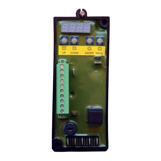
Page 7: Device Description
CENTRO SERVIZI ENERGIA 2. DEVICE DESCRIPTION 2.1 Introduction S2014 is a last generation Automatic Voltage Regulator for Generators excitation control. The unit contains the most advanced microprocessor technology together with IGBT semiconductor technology (Insulated Gate Bipolar Transistor). A practical and simple-to-operate on board panel is used for all control operations. In addition, user friendly software facilitates the commissioning and allows the optimization of the performances. -
Page 8: Overall Dimensions And Fixing Holes
BELTRAME CENTRO SERVIZI ENERGIA 2.4 Overall Dimensions and Fixing Holes Ø5 2.5 Application Area This AVR is used for the excitation of synchronous machines. This unit is suitable for this only application area. The AVR can manage several regulations. Among them: Voltage regulation;... -
Page 9: Basic Insertion Configurations
BELTRAME CENTRO SERVIZI ENERGIA 2.6 Basic Insertion Configurations The following SLD show some basic insertion configurations of the S2014. SM: Synchronous Machine E: Exciter PMG: Permanent-Magnet-Generator D:Direct Current machine S2014 Vsense In this configuration the AVR is powered directly from the generator output (or from an auxiliary winding). -
Page 10: Hardware
Interface with PC (see the dedicated chapter) Parameter setting and optimization is possible using the user-friendly S2014 Config for Microsoft Windows. Using an USB/RS485 cable (made by Beltrame - Optional), with USB insulator, for the connection between PC and AVR, is possible to: •... -
Page 11: Terminal Blocks
BELTRAME CENTRO SERVIZI ENERGIA Terminal blocks Overview of the device connections: Description of the terminals: CN2 – RS 485 Serial Interface CN3 – Control connections Increase reference adjust -RESERVED- Decrease reference adjust LINK – 52G status (parallel feedback) LINK + ±5V analog input... -
Page 12: Device Connections
CENTRO SERVIZI ENERGIA 3. DEVICE CONNECTIONS Required Qualification Personnel involved in installation work and commissioning of the S2014 must be familiar, specially instructed and informed about the residual danger areas according to the regulations currently in force. Only specially instructed personnel must carry out maintenance and repair work. -
Page 13: Device Connections: Cn3 I/O Control Signals
BELTRAME CENTRO SERVIZI ENERGIA 3.3 Device connections: CN3 I/O control signals Terminal Diagram Description designation S2014 CN3 3 programmable digital inputs • 4mA • Up / Down / Increase Decrease programmable function Parallel feedback CN3 Digital inputs • AVR/FCR/PF/VAR mode... -
Page 14: Operating Modes
BELTRAME CENTRO SERVIZI ENERGIA 4. OPERATING MODES S2014 allows bump less changeover between all operation modes: Automatic voltage regulator (AVR) It regulates the output voltage of the synchronous machine. Note: Output Generator Current measurement is optional: it is used only for droop compensation Field Current Regulation (FCR) It regulates the excitation (field) current of the synchronous... -
Page 15: Functions Description
BELTRAME CENTRO SERVIZI ENERGIA 5. FUNCTIONS DESCRIPTION 5.1 Soft Start Setting the following parameters, it is possible to set up the excitation ramp of the Generator (Output Voltage vs Time): Parameter Description (short) Description Gen rated voltage P.100 Generator rated voltage [V] Ramp slope R.002... -
Page 16: Keep Alive
With “keep alive” enabled (P.250>0), the S2014 will try to keep a minimum excitation current during the start-up. As default P.250 is adjusted to 5. This means that the S2014, during the start-up, will try to keep the excitation current to 5% of the rated excitation current (P.000). -
Page 17: Limiters
BELTRAME CENTRO SERVIZI ENERGIA 5.4 Limiters 5.4.1 V/F Limiter The V / Hz limit is active during the voltage control phase. It works by limiting the Generator voltage as the frequency falls below the maximum frequency P.131. This operation can avoid the Generator over-flushing in case of a reduction of speed. -
Page 18: Maximum Excitation Current: Over Excitation Limiter
BELTRAME CENTRO SERVIZI ENERGIA 5.4.3 Maximum excitation current: Over Excitation limiter The limit of maximum excitation current operates a limitation on the maximum excitation current. The limit works in order to avoid to overtake the P.001 value, and if the excitation current remains on P.001 for longer than P.032, the AVR reduce the excitation current to 102%. -
Page 19: Maximum Capability: Q+ Limiter
Q + lim @ P 100% P.171 Limit Q+ a P=100% 5.4.6 S2014 Config: Limits status The S2014 Config software reports an overview of the limiters status: The reported limiters status shows that the V/Hz (underfrequency or underspeed limiter) is active. -
Page 20: Working Mode And Regulations
PF Control [Power Factor Regulator]: S2014 works in order to keep the PF to the ref value VAR Control [Reactive Power Regulator]: S2014 works in order to keep the Reactive Power to the ref value 1. AVR [Automatic Voltage Regulator] r.350... -
Page 21: Automatic Voltage Regulator (Avr)
BELTRAME CENTRO SERVIZI ENERGIA 6.1 Automatic voltage regulator (AVR) The AVR automatically controls the output voltage at the generator terminals. This is the main working mode. The AVR function is active if P300=1. As alternative it is possible to activate the AVR function programming the digital input I002=4, and closing the external contact. -
Page 22: Power Factor Regulation (Pf)
BELTRAME CENTRO SERVIZI ENERGIA 6.3 Power Factor regulation (PF) The AVR controls in automatic mode the power factor at generator terminals. The PF function is active when P300= 1, and I002= 5; once the 52G digital input (generator in parallel) is closed, the PF function starts to work. -
Page 23: Digital Reference Adjustment By Calibrator (Up/Down)
BELTRAME CENTRO SERVIZI ENERGIA 6.5 Digital reference adjustment by calibrator (Up/Down) In AVR mode, by programmed digital inputs (I.000=1 increase, I.001=2 decrease) on CN3 connector, it is possible to adjust the nominal voltage set point in a range between -r.010% and +r.010%. The same function is available in FCR mode, in this case the UP/DOWN input is influencing the excitation current. -
Page 24: Operator Interface
DOWN: allows to move from a parameter or menu to the previous one and/or decrease the value. 7.2 Navigating inside the menus Once the S2014 is ON, the display shows automatically the parameter d100 (Generator voltage). V gen d.100 Menù of ready-only parameters (display) Down Menù... -
Page 25: Parameters Saving
BELTRAME CENTRO SERVIZI ENERGIA Example: how to change the rated voltage generator setting increase To confirm the modifield setting P.100 Exit without saving (It keeps previous value) decrease 7.3 Parameters Saving IMPORTANT: even if the modifications on the parameters are immediately active, they are not automatically saved. -
Page 26: Menù Description
BELTRAME CENTRO SERVIZI ENERGIA 7.4 Menu Description 7.4.1 Menu “D” – Display (readings) DISPLAYS Terminals IPA Description [U.M.] Default Max Notes, values d.000 Field data Field Current 200,0 % of P.000 d.020 Out Duty Cycle 100,0 Generator data d.100 Gener. V % of P.100... -
Page 27: Menù "I" - Inputs And Outputs
BELTRAME CENTRO SERVIZI ENERGIA 7.4.3 Menu “I” – Inputs and Outputs I/Os Name IPA Description [U.M.] Default Max Notes, values Digital inputs I.000 Dig inp 1 cnf 0 NONE 1 INCREASE 2 DECREASE I.001 Dig inp 2 cfg 3 FCR Remote enabling I.002... -
Page 28: Menù "P" - Parameters
Compensation Access control P.981 1022 Password 9999 For S2014 the password is disabled (*) P.110 setting influences the power readings. Following example will help to understand how to manage this setting: - Rated Generator Power = 500kVA - Rated Generator Voltage=... -
Page 29: Trouble Shooting
BELTRAME CENTRO SERVIZI ENERGIA 8. TROUBLE SHOOTING DANGER! The AVR is NOT insulated from the power supply and from field circuit. The maintenance operations MUST be done ONLY when the AVR is disconnected and the protection devices are mounted and/or activated. -
Page 30: Repairing
8.3 Repairing In case it is confirmed that the AVR is defective, we recommend to contact Beltrame CSE to agree about repairing conditions. We strongly recommend to avoid to return back any devices without previous agreement. -
Page 31: Connection Diagram
Only specially instructed personnel must carry out connection and repair activities. Each person involved in the installation and commissioning of the S2014 has to have received the appropriate training or instructions and has thoroughly read and clearly understood the safety instructions reported in this manual. -
Page 32: Basic S2014 Connection Diagrams
CENTRO SERVIZI ENERGIA 9.2 Basic S2014 Connection Diagrams Following diagram shows how to connect the S2014 to a low voltage generator with: Sensing voltage between phase-phase (max 500Vac), L1 and L3 Aux power supply between phase and neutral (max 300Vac) CT mounted on L2 All other combinations can be obtained from this one. -
Page 33: S2014 Connection Diagrams With Low Voltage Alternator
BELTRAME CENTRO SERVIZI ENERGIA 9.3 S2014 Connection Diagrams with Low Voltage Alternator 500 VAC 500 VAC 300 VAC 300 VAC Basic Connection Diagram for LV alternator: LV alternator with PMG: Sensing voltage: phase-phase (max 500Vac) Sensing voltage: phase-phase (max 500Vac) -
Page 34: S2014 Connection Diagrams With Medium Voltage Alternator
BELTRAME CENTRO SERVIZI ENERGIA 9.4 S2014 Connection Diagrams with Medium Voltage Alternator Voltage transformer xxx VAC 500 VAC Input...kV Output 100 VAC xxx VAC 300 VAC 300 VAC MV alternator with PMG: Connection Diagram for MV alternator: Sensing voltage: from Volt Transf. (max 500Vac) Sensing voltage: from Volt Transf. -
Page 35: Beltrame Configurator: The Pc Software
The S2014 Config is useful during the regulator commissioning, or in case of troubleshooting activities. 10.1 Connection between AVR and PC For the PC-AVR connection we recommend the following diagram, with USB isolator Using an USB/RS485 cable (Beltrame’s production – available as optional):... -
Page 36: Parameters Setting: P.xxx And Procedure
BELTRAME CENTRO SERVIZI ENERGIA 10.3 Parameters setting: P.xxx and procedure Press on the “Parameters” label to access to the AVR settings (P.xxx; R.xxx; I.xxx): Recommended procedure for parameters modification: R All: download all the parameters (P, R, I, D) from AVR to PC. -
Page 37: Parameters Setting: L.xxx And R.xxx
BELTRAME CENTRO SERVIZI ENERGIA 10.4 Parameters setting: P.xxx Remaining on the Parameters windows, click on the I label to access to I.xxx setting: As above, remaining on the Parameters windows, click on the R label to access to R.xxx setting:... -
Page 38: Parameters Setting: D
BELTRAME CENTRO SERVIZI ENERGIA 10.5 Parameters setting: D.xxx The D.xxx windows allows to read all the values available on the on board display. To update the values press R Page. The readings can help the troubleshooting activities. 10.6 Regulator Windows... -
Page 39: Trend Window
BELTRAME CENTRO SERVIZI ENERGIA 10.7 Input/Output window Selecting the I/O window, you can access/read the following values: 10.8 Trend window Selecting the Trend window, you have available a powerful tool for commissioning and/or troubleshooting: Above trend shows some step tests (+5% on the reference voltage) effect. - Page 40 BELTRAME CENTRO SERVIZI ENERGIA...
- Page 41 BELTRAME CENTRO SERVIZI ENERGIA...
- Page 42 BELTRAME CENTRO SERVIZI ENERGIA Via San Pio X, 104 BELTRAME C.S.E. s.r.l 35015 Galliera Veneta PD - Italy Tel. +39 049 5965127 beltramecse.com info@beltramecse.com...
Need help?
Do you have a question about the S2014 and is the answer not in the manual?
Questions and answers