Table of Contents
Advertisement
Quick Links
Advertisement
Table of Contents

Related Manuals for AussieCarHoists YL5000


Summary of Contents for AussieCarHoists YL5000
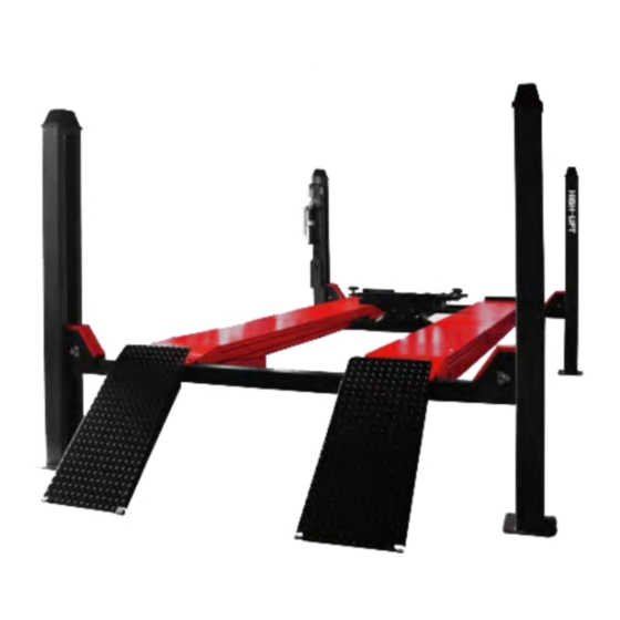
- Page 1 YL5000 Wheel Alignment Four Post Lift Capacity 5000Kg USER’S MANUAL 1 / 32...
-
Page 2: Table Of Contents
Index Chapter 1 General Information ....................4 Manual Keeping ......................4 Obligation in case of malfunction ................. 4 Cautions for the safety of the operator ................5 Warnings ........................5 Chapter 2 Product Identification ....................6 Warranty ........................6 Technical Service ......................6 Chapter 3 Packing, Transport and Storage ................ - Page 3 Controls ........................29 To raise the lift ......................30 To lower the lift ......................30 Jack Operation ......................30 Chapter 9 Maintenance ......................30 Ordinary Maintenance ....................30 Periodic Maintenance ....................30 Chapter 10 Troubleshooting....................31 3 / 32...
-
Page 4: Chapter 1 General Information
Chapter 1 General Information This chapter contains warning instructions to operate the lift properly and prevent injury to operators or objects. This manual has been written to be used by shop technicians in charge of the lift (operator) and routine maintenance technician (maintenance operator). The operating instructions are considered to be an integral part of the machine and must remain with it for its whole useful life. -
Page 5: Cautions For The Safety Of The Operator
Cautions for the safety of the operator Operators must not be under the influence of sedatives, drugs or alcohol when operating the machine. Before operating the lift, operators must be familiar with the position and function of all controls, as well as the machine features shown in the chapter “Operation and use” Warnings Unauthorized changes and/or modifications to the machine relieve the manufacturer of any liability for possible damages to objects or people. -
Page 6: Chapter 2 Product Identification
Chapter 2 Product Identification The identification data of the machine are shown in the label placed on the machine. Below is a blank sample for reference. For the real place please check on the machine. Four Post Lift CE Model No. Power Supply Lift Capacity(Kg) Min Height (mm) -
Page 7: Chapter 3 Packing, Transport And Storage
Chapter 3 Packing, Transport and Storage Packing The packing of the lift is delivered in following components: ⚫ columns wrapped up in non-scratch material sealed with 2 straps, each 2 columns packed in one package ⚫ runways each wrapped up in non-scratch material ⚫... -
Page 8: Chapter 4 Product Description
Chapter 4 Product Description Four Post Lift Rough Description This four post lift has been designed for the lifting of motor-vehicles for wheel alignment and normal maintenance. The maximum lifting weight is as specified on the serial plate. Most of mechanical parts such as runway, transverse beams have been built in steel plate to make the lift stiff and strong while keeping a low weight. -
Page 9: Chapter 5 Technical Specification
Chapter 5 Technical Specification Technical Data Lift Capacity 5000kg Jack Capacity 2500kg Maximum Lifting Height 1800mm Minimum Height 215mm Jack raised height 450mm Runway length 5100mm Runway width 508mm Free width between runways 850-1050mm Width between two columns 2750mm Overall length 5460mm Overall height 2200mm... - Page 10 10 / 32...
-
Page 11: Hydraulic Drawing
Hydraulic Drawing Main hydraulic cylinder Motor Non return valve Gear pump Maximum pressure valve Oil filter Lowering solenoid valve Emergency hand pump - optional Lowering control valve Parachute valve - optional 11 / 32... -
Page 12: Electrical Drawing (380V/400V-3Ph)
Electrical Drawing (380V/400V-3Ph) 12 / 32... -
Page 13: Wiring Diagram
Wiring Diagram 13 / 32... - Page 14 14 / 32...
-
Page 15: Pneumatic Drawing
Pneumatic Drawing Pneumatic cylinders Solenoid air valve Water separator and lubricator Compressed air supply 15 / 32... -
Page 16: Chapter 6 Safety
Chapter 6 Safety Read this chapter carefully and completely because it contains important information for the safety of the operator and the person in charge of maintenance. The lift has been designed and built for lifting vehicles and making them stand above level in a closed area. -
Page 17: Risk Of The Vehicle Falling From The Lift
Risk of the Vehicle falling from the lift Vehicle falling from the lift can be caused when the vehicle is improperly placed on platforms, and when its dimensions are incompatible with the lift or by excessive movement of the vehicle. In this case, keep immediately away from the working area. -
Page 18: Risk For Unauthorized Uses
Risk for unauthorized uses The presence of unauthorized persons next to the lift and on the platforms is strictly forbidden during lifting as well as when the vehicle has been already lifted Risk during vehicle lifting and working 6.10 To avoid overloading and possible breaking during lifting and working, the following safety devices have been used: •... -
Page 19: Chapter 7 Installation
Chapter 7 Installation Only skilled technicians, appointed by the manufacturer, or by authorized dealers, must be allowed to carry out installation. Serious damage to people and to the lift can be caused if installations are made by unskilled personnel. Always refer to the exploded views attached during installation. Tools for installation ✟... - Page 20 20 / 32...
-
Page 21: Installation Of Runways And Transverse Beans
Installation of runways and transverse beans It is important to position the power-side runway (with the hydraulic cylinder) on the same side as the power unit location. The rails on each side must be installed to the inside. • Place each runway on the wooden blocks as shown in the figure, which is suggested to be approximate 100mm high, and position each Runway... -
Page 22: Steel Cable Routing Plan (Very Important)
Steel Cable Routing Plan (Very Important) Please check above drawing: Post “a” is the main post with control part! For more detailed cable rooting please refer to below two pictures. 21 / 32... - Page 23 2 rooting drawing on this page is the same but in different view. Please refer to any one! There will be some initial stretching of the cables in the beginning. It will be necessary to re-adjust the cables a week after the first week, then three to six months thereafter.
-
Page 24: Installation Of Safety Lock
Installation of safety Lock • Once you check below description clearly then it is easy to install/adjust the safety lock.. There are two lock tongues. ⚫ Upper one is working only when the cable get broken suddenly! So please make sure below 2 points a) Make the spring tight so that it is powerful! b) Adjust the tongue to make sure the tip is pointing to the middle of the hole on the lock bar. -
Page 25: Installation Of The Columns
Installation of the columns • Transport the columns to the located site. • Move each column toward the respective end of the transverse beam until stopped by the slide blocks on the transverse beam. Make sure that the power-side column is positioned in the correct location. -
Page 26: Hydraulic System Connection
Hydraulic system connection 7.11 When routing the hydraulic hose, make sure that the hose is clear of any moving part, make sure to keep the hose and fittings clean from dust. Failure to do so may result in hydraulic line failure which may result in damage or personal harm. -
Page 27: Pneumatic System Connection
Pneumatic system connection 7.13 When routing the air tubes, make sure that the tubes are clear of any moving part. It may necessary to tie the tubes clear by using nylon tie straps or wire. Failure to do so may result in safety failure which may result in damage or personal harm. -
Page 28: Check And Adjustment
• Make sure the electrical system feeding voltage is equal to that specified in the nameplate on the motor • Make the lift is connected to the ground • Make sure the working area is free from people and objects •... -
Page 29: Accessories Installation
Accessories Installation 7.18 • Install the front wheel stops. • Install the ramps on the lift. • Install the post cover onto the top of each column. • Install the power unit cover. Check with load 7.19 Warning: please follow carefully the instructions in the coming paragraph for avoiding damages on the lift. -
Page 30: Chapter 8 Operation And Use
Chapter 8 Operation and Use Never operate the lift with any person or equipment below. Never exceed the rate lifting capacity. Always ensure that the safety locks are engaged before any attempt is made to work on or near the vehicle. Never leave the lift in an elevated position unless the safeties are engaged. - Page 31 To raise the lift • Position the vehicle tires in the centre of each runway. • Set parking brake or use wheel chock to hold vehicle in position. • Before raising the vehicle, be sure the safety area is free of people and objects. Pay attention to the overhead clearance.
- Page 32 Chapter 9 Maintenance Only trained people who know how the lift works, must be allowed to service the lift. To service properly the lift, the following has to be carried out: • Use only genuine spare parts as well as equipment suitable for the work required; •...
- Page 33 Chapter 10 Troubleshooting A list of possible troubles and solutions is given below ROUBLE OSSIBLE AUSE OLUTION The main switch is not turned on Turn the switch on Check Power on to restore if There is no power necessary The electrical wires are The lift does not work Reconnect disconnected...
Need help?
Do you have a question about the YL5000 and is the answer not in the manual?
Questions and answers