Advertisement
Quick Links
sauder.com
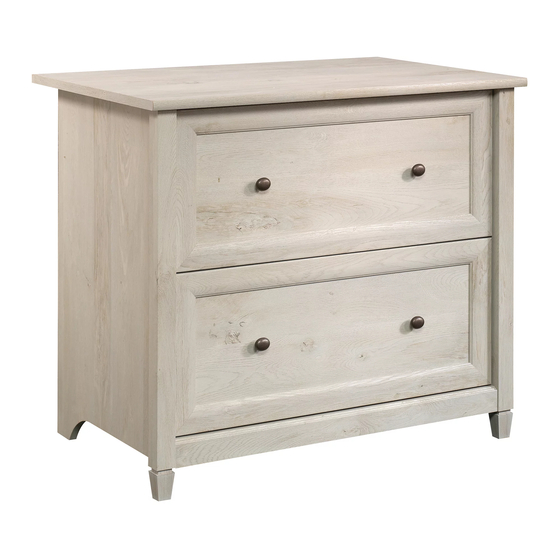
Lateral File
Edge Water Collection | Model 418796
Need help? Visit Sauder.com to view video assembly tips or chat with a live rep.
Prefer the phone? Call 1-800-523-3987.
Share your journey!
Get all organized
and stuff .
NOTE: THIS INSTRUCTION
BOOKLET CONTAINS IMPORTANT
SAFETY INFORMATION.
PLEASE READ AND KEEP FOR
FUTURE REFERENCE.
English pg 1-22
Français pg 23-25
Español pg 26-28
Lot # 385950
10/26/15
Purchased: __________________
Be sure to give us a ring before
making any returns. 1-800-523-3987
Advertisement

Subscribe to Our Youtube Channel
Related Manuals for Sauder Edge Water 418796


Summary of Contents for Sauder Edge Water 418796
- Page 1 Edge Water Collection | Model 418796 NOTE: THIS INSTRUCTION BOOKLET CONTAINS IMPORTANT SAFETY INFORMATION. Need help? Visit Sauder.com to view video assembly tips or chat with a live rep. PLEASE READ AND KEEP FOR FUTURE REFERENCE. Prefer the phone? Call 1-800-523-3987.
- Page 2 Use this part identifi cation to help identify similar parts. RIGHT END (1) DRAWER FRONT (2) LEFT END (1) BOTTOM MOLDING (1) TOP (1) FOOT (2) BOTTOM (1) D225 DRAWER SIDE (4) BACK (1) D243 DRAWER BOX FRONT (4) LEG (2) D928 DRAWER BOTTOM (2) Page 2 418796 www.sauder.com/services...
- Page 3 Part Identifi cation D225 D243 D928 D243 D225 D225 D243 D928 D243 D225 www.sauder.com/services 418796 Page 3...
- Page 4 FILE BRACKET - 4 HIDDEN CAM - 18 CAM DOWEL - 12 CAM SCREW - 6 20G DRAWER STOP - 2 METAL BRACKET - 3 29G SAFETY STOP - 2 124K KNOB - 4 INTERLOCK TRACK - 1 Page 4 418796 www.sauder.com/services...
- Page 5 BLACK 9/16" LARGE HEAD SCREW - 6 BLACK 1-1/4" FLAT HEAD SCREW - 16 BROWN 7/16" LARGE HEAD SCREW - 8 BLACK 7/8" LARGE HEAD SCREW - 8 16S BLACK 1-7/8" PAN HEAD SCREW - 2 BLACK 1-1/8" MACHINE SCREW - 4 www.sauder.com/services 418796 Page 5...
- Page 6 Look for this icon. It means a Step 1 video assembly tip is available at www.sauder.com/services/tips Assemble your unit on a carpeted fl oor or on the empty å carton to avoid scratching your unit or the fl oor. Scan this QR code or go to this address: http://qr.sauder.com/?ID=1460...
- Page 7 Step Step 2 Insert two SAFETY STOPS (29G) into the holes shown in å the RIGHT END (A). This pin must insert into the location holes in the RIGHT END (A). www.sauder.com/services 418796 Page 7...
- Page 8 Visually check that all INTERLOCK TRACK edges have been engaged into the SAFETY STOP as shown å in diagram 3. Then, remove the INTERLOCK TRACK assembly from the END. Do not slide the CABINET ACTUATORS onto the INTERLOCK TRACK. Page 8 418796 www.sauder.com/services...
- Page 9 Fasten the FEET (L) to the LEGS (F2). Use two BLACK å 1-7/8" PAN HEAD SCREWS (16S). (6 used) View after the FOOT is fastened These surfaces must be even. These surfaces must be even. BLACK 1-7/8" PAN HEAD SCREW (2 used in this step) www.sauder.com/services 418796 Page 9...
- Page 10 (8 used in this step) Open end After fastening the RAILS to the ENDS, rest the INTERLOCK TRACK assembly against the RAILS. There should be no more than a 1/16" gap between all ACTUATORS and RAILS. Open end Page 10 418796 www.sauder.com/services...
- Page 11 Tighten Risk of damage or Arrow injury. HIDDEN CAMS must be completely Arrow Maximum tightened. HIDDEN 210 degrees CAMS that are not completely tightened may loosen, and parts may separate. To Minimum completely tighten: 190 degrees www.sauder.com/services 418796 Page 11...
- Page 12 These holes must be here. S u r f a c i t h H I D D E N i t h o f a c S u r D E N H I D Page 12 418796 www.sauder.com/services...
- Page 13 NOTE: Be sure the BRACKETS are even with the edges of å the BOTTOM. Fasten the BOTTOM MOLDING (K) to the METAL å BRACKETS (4G). Use three BLACK 9/16" LARGE HEAD SCREWS (1S). Curved edge BLACK 9/16" LARGE HEAD SCREW (6 used in this step) www.sauder.com/services 418796 Page 13...
- Page 14 å Maximum Arrow Fasten the TOP (C) to the ENDS (A and B). Tighten four å 210 degrees HIDDEN CAMS. Minimum 190 degrees Pro Tip: Lift with your legs. And, you know, your arms. Rounded edge Page 14 418796 www.sauder.com/services...
- Page 15 Repeat this step for the other drawer. å D225 D243 D225 Be sure the grooves in each part line up with each other on the inside of the drawer. BLACK 1-1/4" FLAT HEAD SCREW (8 used in this step) www.sauder.com/services 418796 Page 15...
- Page 16 Fasten a DRAWER BOX FRONT (D243) to the DRAWER å SIDES (D225). Use four BLACK 1-1/4" FLAT HEAD SCREWS (7S). Repeat this step for the other drawer. å D225 D243 D225 D243 D928 BLACK 1-1/4" FLAT HEAD SCREW (8 used in this step) Page 16 418796 www.sauder.com/services...
- Page 17 å BLACK 1-1/8" MACHINE SCREW BLACK 7/8" LARGE HEAD SCREW (4 used for the KNOBS) (8 used for the DRAWER FRONTS) D243 124K The hole on the opposite surface must be close to the bottom edge. www.sauder.com/services 418796 Page 17...
- Page 18 Fasten one of the EXTENSION SLIDES (N) through holes å #2 and #4 to the LEFT DRAWER SIDE (D225). Use two GOLD 5/16" FLAT HEAD SCREWS (3S). GOLD 5/16" FLAT HEAD SCREW (4 used in this step) Open end D225 D225 Page 18 418796 www.sauder.com/services...
- Page 19 Now, fasten this EXTENSION SLIDE (N) to the right DRAWER å SIDE (D225). Use two GOLD 5/16" FLAT HEAD SCREWS (3S). Repeat steps 13 and 14 for the other drawer. å These tabs must insert into the slots. Open end Post D225 D225 Seated D225 www.sauder.com/services 418796 Page 19...
- Page 20 Fasten two FILE BRACKETS (11B) to the DRAWER BOX å FRONTS (D243). Use four BROWN 7/16" LARGE HEAD SCREWS (6S). Repeat this step for the other drawer. å BROWN 7/16" LARGE HEAD SCREW (8 used in this step) D243 Page 20 418796 www.sauder.com/services...
- Page 21 Slide another FILE GLIDE (5B) onto the other end of the å FILE RODS (9B), then press this FILE GLIDE over the LEFT DRAWER SIDE (D225). Repeat this step for the other drawer. å D225 D225 www.sauder.com/services 418796 Page 21...
- Page 22 NOTE: Please read the back pages of the instruction booklet for important safety information. å This completes assembly. Clean with your favorite furniture polish or a damp cloth. Wipe dry. å And to celebrate, why not share your success story? 50 lbs. 40 lbs. 40 lbs. Page 22 418796 www.sauder.com/services...
- Page 23 élément et conserver le livret pour future référence. EXTRÉMITÉ DROITE ............. 1 (ENSEMBLE DE EXTENSION ILLUSTRÉ À PART) Pour contacter Sauder EXTRÉMITÉ GAUCHE ............1 GLISSIÈRE D’EXTENSION ..........4 en ce qui concerne cet DESSUS ..................1 COULISSE D’EXTENSION ..........
- Page 24 Fixer les PIEDS (L) aux PIEDS (F2). Utiliser deux VIS NOIRES TÊTE GOUTTE DE SUIF 48 mm (16S). ÉTAPE 9 Relever, avec précaution, l’élément dans sa position verticale. Fixer le DESSUS (C) aux EXTRÉMITÉS (A et B). Serrer quatre EXCENTRIQUES ESCAMOTABLES. Page 24 418796 www.sauder.com/services...
- Page 25 Maintenant, fi xer cette COULISSE D’EXTENSION (20G) au CÔTÉ DE TIROIR (D225) droit. Utiliser deux VIS DORÉES TÊTE PLATE 8 mm (3S). Répéter les étapes 13 et 14 pour l’ a utre tiroir. www.sauder.com/services 418796 Page 25...
- Page 26 (ENSEMBLE DE EXTENSION ILLUSTRÉ À PART) et conserver le livret pour future référence. EXTREMO IZQUIERDO ............1 RIEL DE EXTENSIÓN .............. 4 Pour contacter Sauder PANEL SUPERIOR ..............1 CORREDERA DE EXTENSIÓN ........4 en ce qui concerne cet FONDO .................... 1 BARRA DE ARCHIVERO ...........
- Page 27 Fije las PATAS (L) a las PATAS (F2). Utilice dos TORNILLOS NEGROS DE PASO 9 CABEZA REDONDA de 48 mm (16S). Cuidadosamente ponga la unidad en posición vertical. Fije el PANEL SUPERIOR (C) a los EXTREMOS (A y B). Apriete cuatro EXCÉNTRICOS ESCONDIDOS. www.sauder.com/services 418796 Page 27...
- Page 28 Ahora fi je esta CORREDERA DE EXTENSIÓN (20G) al LADO DE CAJÓN (D225) derecho. Utilice dos TORNILLOS DORADOS DE CABEZA PERDIDA de 8 mm (3S). Repita los pasos 13 y 14 para el otro cajón. Page 28 418796 www.sauder.com/services...
- Page 29 Les téléviseurs peuvent être très un téléviseur téléviseur. lourds. De plus, le poids et l’emplacement du tube image ont tendance à rendre les téléviseurs instables et enclins à tomber vers l’ a vant. www.sauder.com/services 418796 Page 29...
- Page 30 Además, el peso y la ubicación del tubo de imagen tienden a causar la inestabilidad de televisores y hacerlos propensos a volcarse hacia adelante. Page 30 418796 www.sauder.com/services...
- Page 31 GARANTIE LIMITÉE DE 5 ANS 1. Sauder Woodworking Co. (Sauder®) off re une couverture de garantie limitée à l’ a cheteur 4. La présente garantie ne s’ a pplique qu’ a ux défauts garantis qui se produisent pour initial du présent produit pendant une période de cinq ans à...
- Page 32 Dear Valued Customer: So, how did it go? Thanks so much for choosing Sauder® furniture. I hope the Set a world record for speed? purchase and assembly process was a positive experience Feeling good about yourself? and you feel good about the furniture you just built. If you Nice.
Need help?
Do you have a question about the Edge Water 418796 and is the answer not in the manual?
Questions and answers