Page 1
Translation of original operating instructions for 
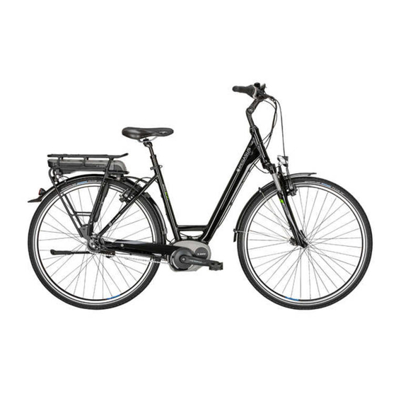
PEGASUS Pedelecs with BOSCH Purion on-board computer Ancura E7R HS, Ancura E8R Disc, Orticello E, Piazza E7 F NL, Swing E7R 20", Swing E8 Disc 20" L L K L K K K K K...
Contents Contents About these operating instructions Manufacturer Laws, standards and directives Language For your information 1.4.1 Warnings 1.4.2 Markups Type number and model Frame number Identifying the operating instructions Aim of the operating instructions Safety Residual risks 2.1.1 Risk of fire and explosion 2.1.1.1 Rechargeable battery 2.1.1.2...
Page 4
Contents 3.6.4 BOSCH Purion on-board computer 3.6.5 Motor 3.6.5.1 Active Line Plus 3.6.6 Rechargeable battery 3.6.6.1 PowerPack 400 3.6.6.2 PowerPack 500 3.6.6.3 PowerTube 400 3.6.6.4 PowerTube 500 3.6.7 Tightening torques Transporting and storing Weight and dimensions for transportation Designated handles, lifting points Transportation 4.3.1 Using the brake transport securing system...
Page 5
Contents 6.5.4.1 Straightening the saddle 6.5.4.2 Eightpins suspension seat post 6.5.4.3 Adjusting the saddle height 6.5.4.4 Setting the saddle height with the remote control 6.5.4.5 Adjusting the saddle position 6.5.4.6 Adjusting the saddle tilt 6.5.4.7 Checking saddle stability 6.5.5 Handlebars 6.5.5.1 Handlebar width 6.5.5.2...
Page 6
Contents 6.16.1 Frame battery 6.16.1.1 Removing the frame battery 6.16.1.2 Inserting the frame battery 6.16.2 Pannier rack battery 6.16.2.1 Removing the pannier rack battery 6.16.2.2 Inserting the pannier rack battery 6.16.3 Integrated battery 6.16.3.1 Removing the integrated battery 6.16.3.2 Inserting the integrated battery 6.16.4 Charging the battery 6.16.5...
Page 7
Contents 7.1.12 Checking the USB cover 7.1.13 Checking the lighting 7.1.14 Checking the brake After each ride 7.2.1 Cleaning the lights and reflectors 7.2.2 Cleaning the suspension fork 7.2.3 Caring for the suspension fork 7.2.4 Cleaning the pedals 7.2.5 Cleaning the brake 7.2.6 Cleaning the suspension seat post 7.2.7...
Page 8
Contents 7.4.17 Caring for the brake 7.4.17.1 Caring for the brake 7.4.18 Lubricating the eightpins seat post tube Maintenance 7.5.1 Wheel 7.5.1.1 Checking the tyre pressure 7.5.1.2 Checking the tyres 7.5.1.3 Checking the rims 7.5.1.4 Checking the nipple holes 7.5.1.5 Checking the nipple well 7.5.1.6 Checking the rim hooks...
Page 9
Contents 8.5.8.3 Suntour suspension seat post 8.5.8.4 Eightpins NGS2 seat post 8.5.8.5 Eightpins H01 seat post 8.5.9 Rear frame damper 8.5.9.1 FOX component-specific maintenance Troubleshooting, fault clearance and repair Troubleshooting and fault clearance 9.1.1 Drive system or on-board computer does not start up 9.1.2 Error message 9.1.3...
About these operating instructions About these operating instructions Manufacturer 1.4.1 Warnings Warnings indicate hazardous situations and ZEG Zweirad-Einkaufs-Genossenschaft eG actions. You will find three warnings in the Longericher Strasse 2 operating instructions: 50739 Köln, Germany WARNING Tel.: +49 221 17959 0 Fax: +49 221 1795931 E-mail:...
Type no. Model Pedelec type owner. The frame number is the most important City and trekking identifier for verifying ownership. 22-15-2164 Ancura E7R HS bicycle City and trekking 22-15-2165 Ancura E8R Disc, Wave Identifying the operating bicycle instructions...
About these operating instructions Aim of the operating instructions These operating instructions are not a substitute for personal instruction by the specialist dealer supplying the bike. These operating instructions Section are an integral part of the pedelec. Therefore, if it is re-sold at a later time, they must be handed over to the subsequent owner.
Safety Safety Residual risks 2.1.1 Risk of fire and explosion Chargers with excessive voltage damage 2.1.1.1 Rechargeable battery batteries. This may cause a fire or an explosion. The safety electronics may fail if the batteries are damaged or faulty. The residual voltage can ...
Safety 2.1.2 Electric shock 2.1.3.3 Incorrect component The wheels are designed exclusively for use with 2.1.2.1 Damage rim brakes or disc brakes. The wheel may break if Damaged chargers, cables and plug connectors an incorrect brake is used. This will cause a crash increase the risk of electric shock.
Safety Toxic substances Requirements for riders 2.2.1 Brake fluid The rider must have the required mental capacity and physical and motor skills to ride on public Brake fluid may leak out after an accident or due roads. A minimum age of 14 years is to material fatigue.
Safety Safety markings and safety What to do in an emergency instructions 2.8.1 Dangerous situation in road traffic The pedelec and battery nameplates contain In the event of any hazards or dangers in road these safety markings and safety instructions: traffic, apply the brakes on the pedelec until it comes to a halt.
Safety 2.8.4 Battery fire After swallowing Rinse out mouth with water. Never induce The safety electronics may fail if the battery is vomiting. Risk of aspiration. damaged or faulty. The residual voltage can cause a short circuit. The battery may self-ignite ...
Description Description Proper use All check lists and instructions for actions in these regulations for the prevention of accidents and operating instructions must be met. Approved environmental protection in the respective country accessories can be installed by specialist staff. of use must be adhered to. Use the pedelec when it is in perfect, proper The rechargeable batteries are designed to working order only.
Description 3.1.1 Improper use Failure to adhere to the proper use poses a risk of • lending the pedelec to untrained riders • carrying other people personal injury and material damage. It is • riding with excessive baggage prohibited to use the pedelec in the following •...
Description 3.1.3 Environmental requirements You can be ride the pedelec within a temperature Temperatures under -5 °C and over +40 °C must range between -5 °C and +40 °C. The electric be avoided. drive system is limited in its performance outside You must also keep within the following this temperature range.
Page 23
Description The pedelec is unsuitable for the following areas of use: Child's bicycles/ City and trekking Area of use bicycles for Mountain bikes Racing bicycle Cargo bike Folding bicycle bicycles young adults Never drive off-road Never drive off-road Never drive off-road Never drive off-road Never drive off-road or perform jumps.
Overview Nameplate The nameplate is situated on the frame. The Figure 1. The nameplate contains thirteen pieces precise position of the nameplate is shown in of information. ZEG Zweirad-Einkaufs- Genossenschaft eG Longericher Str. 2 50739 Köln, Germany Typ: 22-17-1017 EPAC nach EN 15194 0,25 kW / 25 km/h...
Description Components 3.3.1 Overview Figure 2: Pedelec viewed from the right Front wheel Frame Kickstand Front wheel hub Seat post Shifting hub Fork Saddle Chain guard Front wheel brake Pannier rack Frame number Front wheel mudguard Rechargeable battery Motor and motor cover Front light Rear light Pedal...
Description 3.3.2 Chassis The chassis comprises two components: • Frame and • steering system. 3.3.2.1 Frame The frame absorbs all forces which act on the pedelec from body weight, pedalling and the ground. The frame also acts as a carrier for most components.
Description 3.3.2.5 Handlebars 3.3.2.6 Fork The stem and handlebars are attached to the top The pedelec is steered using the handlebars. The end of the fork steerer. The axle is fastened to the handlebars are used to support the upper body fork ends.
Description 3.3.3 Suspension Both forks and suspension forks are fitted in this model series. 3.3.3.1 Rigid fork Rigid forks do not feature suspension. They transfer the used muscle and motor power to the road to optimum effect. Pedelecs with rigid forks consume less energy on steep roads and have a greater range than pedelecs with suspension.
Page 29
Description Negative deflection (sag) The negative deflection (sag) is the percentage of optimally adjusted. The wheel stays in contact total deflection that is compressed by body with the ground when passing over bumps (blue weight, including equipment (such as a line).
Page 30
Description Rebound damping Only applies to pedelecs with this equipment Rebound damping defines the speed at which the Rebound damping needs to be increased to suspension rebounds after being loaded. achieve an optimal setting if the air pressure or Rebound damping controls the suspension fork spring stiffness are increased.
Page 31
Description Steel suspension fork structure Air suspension fork structure The stem and the handlebars are fastened to the Depending on the model, the air suspension fork has either fork steerer. The wheel is fastened to the axle. • an air suspension assembly group (orange) and/ •...
Description 3.3.4 Wheel If a tyre with a deep tread is used on asphalt, this may make an unpleasant noise when the brakes are used In such a case, the specialist dealer needs to replace the tyre with a new one with a shallow tread.
Description The pedelec has either: Schrader valve • a conventional valve The Schrader valve can be pumped at filling • a Presta valve or stations. Older and easy bicycle pumps are • a Schrader valve. unsuitable for filling tyres via a Schrader valve. Dunlop valve The Dunlop valve, also known as a conventional valve, is the valve in most widespread use.
Description 3.3.5 Braking system A pedelec's brake system is primarily operated 3.3.5.2 Hydraulic brake using the brake lever on the handlebars. The brake fluid is in a closed hose system. If the brake lever is pulled, the brake fluid transfers •...
Description 3.3.5.3 Disc brake Figure 22: Brake system with disc brake – example Brake disc Brake calliper with brake linings Handlebars with brake lever Front wheel brake disc Rear wheel brake disc On a pedelec with a disc brake, the brake disc is screwed permanently to the wheel hub.
Description 3.3.5.4 Rim brake Figure 23: Brake system with rim brake in detail – MAGURA HS22 used as an example Rear wheel rim brake The rim brake stops the wheel moving when the Brake lining rider pulls the brake lever, causing two brake Brake booster linings, positioned opposite one another, to press Handlebars with brake lever...
Description 3.3.5.5 Back-pedal brake Figure 25: Brake system with a back-pedal brake – example Rear wheel rim brake Handlebars with brake lever Front wheel rim brake Pedal Back-pedal brake The back-pedal brake stops the rear wheel from moving by pushing the pedals in the opposite direction to the direction of travel.
Description 3.3.6 Seat post Seat posts are not designed to fasten the saddle Patent saddle posts are fastened into the seat but also to adjust exactly to the optimum sitting tube with either a quick release or a screwable position. The seat post can: clamp.
Description 3.3.7 Mechanical drive system The pedelec is driven by muscle power, just like a 3.3.7.1 Chain drive layout bicycle. The force which is applied by pedalling in the direction of travel drives the front chain wheel. The chain or belt transmits the force onto the rear chain wheel and then onto the rear wheel.
Description 3.3.8 Electric drive system The pedelec has an electric drive system in The pedelec does not have a separate emergency addition to a mechanical one. shut-off button. In the event of an emergency, the motor can be stopped by removing the on-board computer.
Description Battery performance is reduced when the 3.3.8.4 Pannier rack battery temperature drops since this increases electrical Three different types of pannier rack batteries can resistance. As a result, you can expect the range be fitted: to be shorter than normal in winter. We recommend using thermal protection sleeves when riding longer distances in the cold.
Description 3.3.9 Lighting 3.3.8.5 Integrated battery Four different types of pannier rack batteries can When the riding light is activated, the front light be fitted: and the rear light are switched on together. PowerTube PowerTube PowerTube PowerTube (vertical and horizontal) Figure 36: Overview of integrated battery Figure 37: Integrated battery in detail Battery key...
Overview 3.3.10 On-board computer The pedelec has a BOSCH Purion on-board computer. The on-board computer controls the drive system and shows the journey data on the display screen. The battery powers the on-board computer. The on-board computer also has two internal non- rechargeable coin cells.
Overview Description of controls and screens 3.4.1 Handlebars Figure 39: Detailed view of handlebars from sitting position, example Rear wheel hand brake On-board computer Bell Lockout Headlight Shifter Front wheel hand brake MY22P01 - 22_1.0_22.08.2021...
Overview On-board computer The on-board computer is operated using four 3.5.1 Display buttons on its casing. The display has nine on-screen indicators: L L K L K K K K K K K K W W A W W W W W W A A Figure 40: BOSCH Purion on-board computer layout Figure 41: Display overview Indicator for km/h or mph (see Section...
Overview 3.5.1.3 Information display 3.5.1.5 Riding light symbol The display shows one of three types of The riding light symbol is shown when the information. The displayed information can be riding light is on. changed. 3.5.1.6 Maintenance indicator Display Function Indicates that maintenance is required.
Description 3.5.3 Gear shift 3.5.3.1 SHIMANO derailleur gears Only applies to vehicles with this equipment The gear shift is on the right of the handlebars. SHIMANO SL-M3100 gear shift The gear shift has one or two shifters. SHIMANO SL-M315 gear shift Figure 43: Example of SHIMANO SL-M3100 Shifter A Shifter B (optional)
Description 3.5.3.2 SHIMANO hub gear Only applies to vehicles with this equipment SHIMANO hub gears feature a twist grip with a display on the right-hand side of the handlebars. Figure 45: SHIMANO SL-C30000-7O gear shift Twist grip Figure 44: SHIMANO SL-C30000-7 gear shift, top view Gear indicator Twist grip Gear cable outer sleeve...
Description 3.5.4 Hand brake There is a hand brake on the left and right of the handlebars. Figure 46: Front wheel (2) and rear (1) brake levers – Shimano brake used as an example • The left-hand brake controls the front wheel brake.
Description 3.5.5 Battery level indicator (battery) Each battery has its own level indicator: 3.5.5.1 Battery level indicator (battery) The five green LEDs on the battery level indicator show the charge level when the battery is switched on. Each LED represents 20% of battery capacity. LED 1,2,3,4,5 Battery level 100…80%...
Description Technical data 3.6.1 Pedelec 3.6.5 Motor Power output/system 250 W (0.25 kW) 3.6.5.1 Active Line Plus Shut-off speed 25 km/h Maximum continuous power rating 250 W Table 16: Pedelec technical data Max. torque 50 Nm 3.6.2 Emissions Nominal voltage 36 V DC Protection class IP54...
Description 3.6.6.3 PowerTube 400 3.6.6.4 PowerTube 500 Nominal voltage 36 V Nominal voltage 36 V Nominal capacity 11 Ah Nominal capacity 13.4 Ah Energy 400 Wh Energy 500 Wh Weight 2.9 kg Weight 2.9 kg Protection class IP54 Protection class IP54 Operating temperature -5…...
Description 3.6.7 Tightening torques Model Tightening torque Screw On-board computer SC-E5003 Attachment screw 0.8 Nm 3 mm hex bit Shifter SHIMANO DEORE SL-M4100 Attachment screw 3 Nm 4 mm hex bit SHIMANO DEORE SL-M5100 Attachment screw 3 Nm 4 mm hex bit SHIMANO DEORE SL-M6100 Attachment screw 3 Nm...
Page 54
Description eightpins H01 Seat post axle 8 Nm 6 mm hex bit Slipper clutch 18 Nm 3 mm hex bit Valve cover 0.5 Nm 5 mm hex bit Postpin axle 8 Nm 5 mm hex bit Rear clamping screw (saddle) 8 Nm 3 mm hex bit M5 attachment screw for outer sleeve...
Transporting and storing Transporting and storing Weight and dimensions for transportation Weight and dimensions during transport: 22-15-4013 22-15-2138 22-15-2094 22-15-2095 Table 26: Type number, model and pedelec type **Vehicle weight without battery # Not yet available when the instructions were produced Designated handles, lifting points The box does not have any handles.
Transporting and storing Transportation 4.3.2 Transporting the pedelec Bicycle rack systems which use the handlebars or CAUTION frame to hold the pedelec in an upside-down position exert inadmissible forces on its components during transportation. This can cause Crash caused by unintentional activation the supporting parts to break.
Transporting and storing Storing Store pedelec, on-board computer, battery and 4.4.1.1 Preparing a break in operation charger in a clean, dry place where they are Remove the rechargeable battery from the protected from sunlight. Do not store outdoors pedelec.
Assembly Assembly Scope of delivery WARNING 1 pre-assembled pedelec 1 front wheel Risk of eye injury Problems may arise if components are set 2 pedals incorrectly. They may cause serious injuries to 2 quick releases (optional) the face.
Assembly Commissioning Only trained specialist staff may perform initial commissioning since initial commissioning of the pedelec requires special tools and specialist knowledge. Experience has shown that a pedelec which has not yet been sold is automatically handed to customers as soon as it appears ready to ride. ...
Assembly 5.3.2 Preparing the battery 5.3.2.1 Retrofitting the PowerTube adapter Only applies to pedelecs with this equipment A PowerTube Adapter 400 or 500 needs to be 3 Use a ratchet to remove the two 4 mm hexagon retrofitted to use a BOSCH PowerTube 625 screws in the PowerTube adapter.
Page 61
Assembly 6 Use a TORX® T25 wrench to fasten the screws into the battery mount. Figure 57: Fastening the battery mount MY22P01 - 22_1.0_22.08.2021...
Assembly 5.3.2.2 Fit battery cover onto Bosch PowerTube 625 battery (horizontal) Only applies to pedelecs with this equipment 1 Detach the upper interface (lock side) from the 3 Press to push the battery cover onto the BOSCH PowerTube 625 battery with a TORX® battery.
Assembly 5.3.2.3 Fit battery cover onto Bosch PowerTube 500 battery (horizontal) Only applies to pedelecs with this equipment 1 Detach the upper interface (lock side) from the 3 Screw the battery mounting plate onto the BOSCH PowerTube 625 battery with a TORX® PowerTube extension with original BOSCH T20 wrench.
Assembly 5.3.3 Installing the wheel in the SUNTOUR fork Only applies to Suntour forks with this equipment 5.3.3.1 Screw-on axle (12AH2 and 15AH2) Only applies to Suntour forks with this equipment 4 Insert the securing screw on the non-drive side. ...
Assembly 5.3.3.2 20 mm cross axle Only applies to Suntour forks with this equipment 2 Tighten the cross axle with the red handle. CAUTION Crash caused by loose quick release axle A faulty or incorrectly installed cross axle may become caught in the brake disc and block the wheel.
Page 66
Assembly 5 Check the position and clamping force of the quick release lever. The quick release lever must be flush with the shock absorber. Figure 73: Perfect position for the clamping lever 6 Use 4 mm hexagon socket spanner to adjust the clamping lever clamping force if required.
Assembly 5.3.3.3 Q-LOC quick release Only applies to Suntour forks with this equipment 1 Push in the quick release until you can hear a click. Make sure that the flange is extended. CAUTION Crash caused by unfastened quick release A faulty or incorrectly installed quick release may become caught in the brake disc and block the wheel.
Assembly 5.3.4 Preparing the wheel There is an arrow on the sides of the tyres with the inscription ROTATION to show the direction of rotation. The inscription says DRIVE on older tyres. The rotation direction arrow indicates the recommended direction of rotation. On road tyres, the direction of rotation is mainly for optical reasons.
Assembly 5.3.5 Preparing the LIMOTEC seat post Only applies to pedelecs with this equipment 1 Use the seat height formula to calculate the optimum seat post height for the length of rider's leg: Seat height (SH) = inner leg length (I) × 0.9 2 Lower the seat post further into the seat tube 3 The seat post Bowden cable must be tightened in the frame up to the remote control to the...
Assembly 5.3.6 Fitting the pedals The pedals have two different threads to ensure 3 Turn the pedal marked R anti-clockwise by they don’t come loose while the rider is pedalling. hand into the crank arm on the right as seen when facing the direction of travel.
Assembly 5.3.7 Checking the stem and handlebars 5.3.7.1 Checking the connections 5.3.7.3 Checking the headset backlash 1 Stand in front of the pedelec. Clamp the front 1 Place the fingers of one hand on the upper wheel between your legs. Grasp the handlebar headset cup.
Operation Operation Risks and hazards WARNING WARNING Injuries and death caused by distraction Injuries and fatalities caused by blind spots A lack of concentration while riding increases the Other road users, trucks, cars and pedestrians risk of an accident. This may cause a crash with often underestimate the speed of pedelecs.
Page 73
Operation CAUTION CAUTION Crash caused by material fatigue Crash caused by soiling Intensive use can cause material fatigue. A Heavy soiling can impair pedelec functions, such component may suddenly fail in case of material as braking. This may cause a crash with injuries. fatigue.
Operation Tips for a greater range The pedelec's range depends on many Gear shift influencing factors. A single battery charge may Use a low gear and a low level of assistance on only last fewer than 20 kilometres but much more hills and when setting off.
Operation Error message 6.3.1 On-board computer The drive system monitors itself continuously and Code Description Method of resolution displays a number as an error message if a known Battery internal error Re-start the system. error is detected. The system may switch off Contact your specialist automatically depending on the type of error.
Page 76
Operation Code Description Method of resolution Code Description Method of resolution Battery error Switch off system. 595, Communication error Check cabling to the gears. Remove the battery. Re-start the system. Re-insert battery. Contact your specialist Restart electric drive dealer if the problem system.
Page 77
Operation Code Description Method of resolution Code Description Method of resolution Internal fault Re-start the system. 860, Error in the power Re-start the system. supply Contact your specialist Contact your specialist dealer if the problem dealer if the problem persists. persists.
Operation 6.3.2 Rechargeable battery The battery is protected against deep discharge, overcharging, overheating and short circuits by Electronic Cell Protection (ECP). In the event of a hazard, a protective circuit switches the battery off automatically. If a fault is detected in the battery, the LEDs flash on the battery level indicator.
Operation Instruction and customer service The supplying specialist dealer will provide 6.5.1 Preparing customer service. Contact details can be found on The following tools are required to adjust the the pedelec pass for these operating instructions. pedelec: The specialist dealer will explain all the pedelec functions to the new owner in person, this being when the specialist dealer hands over the pedelec Tape measure...
Operation 6.5.3 Determining the sitting position The starting point for a comfortable posture is the Position on roadster Position on city bike correct position of the pelvis. If the pelvis is in the wrong position, it can cause different types of pain, e.g.
Operation 6.5.4 Adjusting the saddle 6.5.4.1 Straightening the saddle 6.5.4.3 Adjusting the saddle height Position saddle in direction of travel. In doing To adjust the saddle height safely, either: so, align the tip of the saddle with the top tube. •...
Operation 5 Open the quick release on the seat post to 6.5.4.4 Setting the saddle height with the remote control change the seat height (1). To do so, push the clamping lever away from the seat post (3). Use the seat height formula to set the saddle height: Seat height (SH) = inner leg length (I) ×...
Operation 6.5.4.5 Adjusting the saddle position 3 Unfasten and adjust the designated screw connections, and clamp them with the The saddle can be shifted on the saddle frame. maximum tightening torque for the saddle The right horizontal position ensures an optimal clamping screws.
Operation 6.5.5 Handlebars Check handlebar width and hand position. The narrower the shoulders are, the greater the bend of the handlebars should be (maximum 28°). Choose different handlebars if necessary. Contact specialist dealer. Straight handlebars are advisable for sports bikes (e.g.
Operation 6.5.6 Stem 6.5.6.1 Adjusting the handlebar height with Adjusting the quick release clamping force quick release Only applies to pedelecs with this equipment CAUTION 1 Open the stem clamping lever. Crash caused by incorrectly set clamping force Applying excessive clamping force damages the quick release.
Operation 6.5.6.2 Setting the quill stem 6.5.6.3 Adjusting the Ahead stem Only applies to pedelecs with this equipment Only applies to pedelecs with this equipment In the case of a quill stem, the stem and fork In the case of an Ahead stem, the stem is placed steerer form a permanently interconnected directly on the fork steerer, which protrudes over component, which is clamped in the fork steerer.
Operation 6.5.6.4 Adjusting the angle-adjustable stem Only applies to pedelecs with this equipment Angle-adjustable stems are available in different lengths for quill and Ahead stems. Figure 99: Different versions of angle-adjustable stems Adjusting the stem angle (c) changes both the distance from the upper body to the handlebars (b) and the handlebar height (a).
Operation 6.5.7 Ergonomic handles In the case of ergonomically shaped handles, the palm rests on the anatomically shaped handle. A greater contact surface means that the pressure is more evenly distributed. Nerves and vessels are no longer squeezed in the carpal tunnel. Figure 101: Correct (1) and incorrect (2) position of the handle 1 Undo the handle screw.
Operation 6.5.8 Tyres It is not possible to offer a general recommended Tyre pressure in bar for body tyre pressure for a particular pedelec or tyre. The weight correct tyre pressure largely depends on the Tyre width about about about weight load on the tyres, mainly determined by 60 kg 80 kg...
Operation 6.5.9 Brake The brake lever grip distance can be adjusted to 6.5.9.2 Brake handle tilt angle ensure that it can be reached more easily. The The nerves that pass through the carpal tunnel pressure point can also be adjusted to the rider's are connected to the thumb and the index and preferences.
Operation 2 Set the brake lever angle as indicated in the table. 20 – 25° > 10 cm 25 – 30° 0 – 10 cm 30 – 35° 0 – 10 cm 35 – 45° > 10 cm Saddle-handlebar height Brake angle difference (mm) >10...
Operation 6.5.9.4 Grip distance on a MAGURA disc brake lever Only applies to pedelecs with this equipment affect the pressure point or the position of the WARNING brake linings. Turn the setting screw/twist knob (5) anti- Crash caused by incorrectly set grip distance clockwise towards minus (–).
Operation 6.5.9.5 Retracting the brake linings Disc brakes require wearing-in time. The braking force increases over time. The braking force is increased during break-in time. This is also the case when the brake pads or brake discs are replaced. 1 Accelerate pedelec to 25 km/h. 2 Brake pedelec until it comes to a halt.
Operation 6.5.10 Suspension A pedelec’s fork suspension and rear frame Follow the the correct order for adjustment. damper suspension can be adjusted to the rider's weight in up to six increments, depending on the suspension system. For pedelecs with components only Rear frame Sequence Adjustment...
Operation 6.5.11.1 Adjusting the Suntour fork steel suspension Only applies to pedelecs with this equipment 1 You will find the sag setting wheel (1) beneath the plastic cover on the crown. Remove the plastic cover. Figure 109: Sag setting wheel (1) on the suspension fork crown ...
Operation 6.5.11.2 Adjusting the Suntour fork air suspension Only applies to pedelecs with this equipment The air valve is located beneath the air valve 1 Attach a high-pressure damper pump to the air cap on the crown. Twist off the air valve cap. valve.
Operation 6.5.12 Fork rebound damping Only applies to pedelecs with this equipment Rebound damping in the suspension fork and the Rebound damping needs to be increased to rear frame damper determines the speed at which achieve an optimal setting if the air pressure or the rear frame damper rebounds after being spring stiffness are increased.
Operation 6.5.12.1 Adjusting the Suntour fork rebound damping Only applies to pedelecs with this equipment Figure 112: Example of Suntour rebound screw (1) The fork sag is adjusted. 1 Turn the rebound screw in a clockwise direction to the closed position until it stops. 2 Turn the rebound screw slightly in an anti- clockwise direction.
Operation 6.5.13 Lighting Example 1 If the front light is positioned too high, oncoming traffic will be dazzled. This can cause a serious accident with fatalities. Example 2 Positioning the front light correctly can ensure that oncoming traffic is not dazzled and no-one is put at risk. Example 3 If the front light is positioned too low, the space ahead is not illuminated to an optimum extent and the rider's vision is reduced in the dark.
Page 101
Operation 4 Place pedelec 5 m from the wall. 6 Switch on riding light. 5 Stand the pedelec up straight. Hold the handlebars straight with both hands. Do not use the kickstand. Figure 115: Light positioned too high (1), correctly (2) and too low (3) 7 Check the position of the light beam.
Operation 6.5.14 On-board computer The on-board computer is operated using four 6.5.14.1 Changing the tachometer unit buttons on its casing. The displayed values can be changed from kilometres to miles. 1 Keep minus button pressed down. 2 Press On-Off button (on-board computer) briefly.
Operation Accessories We recommend a parking stand into which either the front wheel or rear wheel can be inserted CAUTION securely for pedelecs which do not have a kickstand. The following accessories are Risk of crushing due to exposed springs recommended: The child may crush his/her fingers on exposed Description...
Operation 6.6.2 Trailer 6.6.2.1 Approval for trailer with Enviolo hub Only applies to pedelecs with this equipment CAUTION Only compatible bicycle trailers are approved for ENVIOLO hub gears. Crash caused by brake failure KETTLER The braking distance may be longer if the trailer is carrying excessive load.
Operation 6.6.4 Tubeless and airless tyres 6.6.2.2 Approval for trailer with ROHLOFF hub Only applies to pedelecs with this equipment Bicycle riding without tubes reduces the risk of tyre punctures or even avoids them completely. ROHLOFF Speedhub 500/14 The specialist dealer will advise on choosing a As a basic rule, it is permitted to use a trailer suitable tyre system for the pedelec.
Operation Personal protective equipment and accessories for road safety Seeing and being seen is crucial in road traffic. 7 The two separate brakes on the pedelec must The following requirements must be met for riding work at all times. a road-safe vehicle on public roads. 8 The clear sounding bell must be fitted and must work.
Operation Straightening the quickly 6.10 Using the pannier rack adjustable stem CAUTION Only applies to pedelecs with this equipment 1 Open stem clamping lever. Crash caused by loaded pannier rack The pedelec is handled differently with a loaded pannier rack, in particular when the rider needs to steer and brake.
Operation 6.13 Using the pedals The ball of the foot is placed on the pedal when riding and pedalling. Figure 122: The maximum load bearing (1) capacity is indicated on the pannier rack. Never exceed the maximum permitted total weight when packing the pannier.
Operation 6.16 Using the battery Switch off the battery and the drive system before 6.16.2 Pannier rack battery removing or inserting the battery. Only applies to pedelecs with this equipment 6.16.2.1 Removing the pannier rack battery 6.16.1 Frame battery Only applies to pedelecs with this equipment 6.16.1.1 Removing the frame battery Figure 125: Removing (2) and inserting (3) the pannier...
Page 110
Operation 6.16.3 Integrated battery Only applies to pedelecs with this equipment 6.16.3.1 Removing the integrated battery 6.16.3.2 Inserting the integrated battery Figure 127: Inserting the integrated battery Figure 126: Removing the integrated battery 1 Place the battery into the integrated battery 1 Open battery lock with battery key (1).
Page 111
Operation 6.16.4 Charging the battery 6.16.5 Charging the dual battery The ambient temperature during the charging Only applies to pedelecs with this equipment process must be within the range from 0 °C to 40 °C. Notice The battery can remain on the pedelec or can be removed for charging.
Page 112
Operation 6.16.6 Using double battery model with a single battery only One of the charging sockets is not accessible or is sealed with an end cap on pedelecs with two batteries. Figure 128: Covering open contacts with cover cap – example: pannier rack battery ...
Page 113
Operation 6.17 Using pedelec with the electric drive system 6.17.1 Switching on the electric drive system system As soon as you stop pushing the pedals in normal mode or reach a speed of 25 km/h, the drive CAUTION system switches off the assistance system. The assistance system starts up again when you push the pedals and your speed is less than 25 km/h.
Page 114
Operation 6.18 On-board computer 6.18.1 Actions on the on-board computer Notice Action Button Duration Never use the display as a handle. The display Switching on the on-board Brief computer may become irreparably damaged if you use it to lift the pedelec. Switching off the on-board Brief (<...
Page 115
Operation 6.18.5 Using the push assist system 6.18.6 Selecting the level of assistance Press plus button briefly. CAUTION The level of assistance is increased. Press minus button briefly. Injury from pedals or wheels The level of assistance is reduced. The pedals and the drive wheel turn when the push assist system is used.
Page 116
Operation 6.18.8 Replacing the battery 6.18.9 Using the USB port If the on-board computer shows LOW BAT on the Notice display screen, the battery is flat and must be replaced. The USB port is reserved to connect diagnostics The recommended CR 2016 battery can be systems.
Page 117
Operation 6.19 Brake 6.19.1 Using the brake lever Only applies to pedelecs with this equipment WARNING Crash caused by brake failure Oil or lubricant on the brake disc in a disc brake or on the rim of a rim brake can cause the brake to fail completely.
Page 118
Operation 6.20 Suspension and damping Compression adjuster set to hard Compression adjuster set to soft • Causes the suspension fork to move higher within • Causes the fork to deflect quickly and easily. This the deflection range. This improves efficiency, makes it easier to maintain speed and maintains momentum and makes it easier to ride momentum when riding over uneven rugged...
Page 119
Operation 6.20.1 Adjusting the Suntour compression adjuster Figure 133: Suntour compression adjuster in open (1) and closed (2) position Place compression adjuster in the OPEN position. The compression adjuster is open. Place compression adjuster in the LOCK position.
Page 120
Operation 6.21 Gear shift The selection of the appropriate gear is a Lever A switches from a smaller pinion to a larger prerequisite for a physically comfortable ride and one. The number of pinions switched depends on making sure that the electric drive system the selected position of lever A.
Page 121
Operation 6.21.2 Using a SHIMANO hub gear Only applies to pedelecs with this equipment CAUTION Crash caused by incorrect use If the rider applies too much pressure on the pedals during a gear change and activates the shifter or changes several gears at a time, their feet may slip from the pedals.
Page 122
Operation 6.21.3 Using eShift 6.21.3.2 eShift with manual SHIMANO DI2 hub gears eShift refers to the integration of electronic gear Only applies to pedelecs with this equipment shift systems into the electric drive system. The new gear is shown briefly on the on-board 6.21.3.1 eShift with SHIMANO DI2 automatic hub computer each time it is changed.
Page 123
Operation 6.22 Parking 6 Remove the on-board computer (see Notice Section 6.18.1.1), battery (see Section 6.16.1.1, 6.16.2.1 or 6.16.3.1) and mobile phone to Heat or direct sunlight can cause the tyre pressure protect against theft. to increase above the permitted maximum 7 Clean and service pedelec after every ride;...
Page 124
Operation 2 Pull handlebars into highest possible position. Figure 138: All Up pulled into highest possible position 3 Turn handlebars 90° in a clockwise direction. Figure 139: All Up screwed in 4 Place handlebars at required height 5 Close stem clamping lever. MY22P01 - 22_1.0_22.08.2021...
Page 125
Cleaning, servicing and maintenance Cleaning, servicing and maintenance Clean, service and maintain pedelec as indicated on check list. Complying with these measures is the only way to reduce wear on components, increase the operating hours and guarantee safety. Check list before each ride Check list for weekly tasks Check everything is sufficiently Clean chain...
Page 126
Cleaning, servicing and maintenance Check list for monthly tasks Check list for monthly tasks Cleaning the battery Section 7.3.2 Clean hub Section 7.3.12 Clean control panel Section 7.3.1 Cleaning the frame Section 7.3.4 Clean on-board computer Section 7.3.1 Clean tyres Section 7.3.10...
Page 127
Cleaning, servicing and maintenance Check list for tasks to do every six months (or every 1,000 Check list for tasks to do every six months (or every 1,000 Check Bowden cables gear Check steering headset Section 8.5.6 Section 7.5.10.2 shift ...
Page 128
Cleaning, servicing and maintenance CAUTION WARNING Crash and falling caused by unintentional Crash caused by brake failure activation Oil or lubricant on the brake disc in a disc brake There is a risk of injury if the drive system is or on the rim of a rim brake can cause the brake activated unintentionally.
Page 129
Cleaning and servicing Before each ride Complying with these cleaning instructions is the 7.1.5 Checking the pannier rack only way to reduce wear on components, increase 1 Hold onto pedelec by its frame. Hold onto the operating hours and guarantee safety. pannier rack with the other hand.
Page 130
Cleaning and servicing 7.1.10 Checking the bell 1 Press the bell button downwards. 2 Let button spring back. If you do not hear a clear, distinct ring of the bell, replace bell. Contact specialist dealer. 7.1.11 Checking the handles ...
Page 131
Cleaning and servicing After each ride Complying with these cleaning instructions is the 7.2.5 Cleaning the brake only way to reduce wear on components, increase the operating hours and guarantee safety. The following items should be ready for use to ...
Page 132
Cleaning and servicing Basic cleaning Complying with these basic cleaning instructions 7.3.2 Rechargeable battery is the only way to reduce wear on components, increase the operating hours and guarantee safety. The following are required for basic cleaning: CAUTION Tool Cleaning agent Risk of fire and explosion due to penetration by water The battery is only protected from simple spray...
Page 133
Cleaning and servicing 7.3.4 Frame, fork, pannier rack, guards 7.3.7.1 Leather handles and kickstand Leather is a natural product and has similar properties to human skin. Regular cleaning and care help to prevent leather dehydrating, fading or becoming brittle or stained. 1 Soak the components with dish-washing detergent if the dirt is thick and ingrained.
Page 134
Cleaning and servicing 7.3.9.1 Leather saddle 7.3.12 Hub Leather is a natural product and has similar 1 Put on protective gloves. properties to human skin. Regular cleaning and 2 Remove dirt from hub with a sponge and soapy care help to prevent leather dehydrating, fading or water.
Page 135
Cleaning and servicing 7.3.15 Brake 7.3.18 Chain 7.3.15.1 Brake lever Notice Carefully clean the brake levers with a damp, soft cloth. Never use aggressive (acid-based) cleaners, rust removers or degreasers when cleaning 7.3.16 Brake disc the chain. Never use gun oil or rust remover spray. ...
Page 136
Cleaning and servicing Servicing Complying with these servicing instructions is the 7.4.1 Frame only way to reduce wear on components, increase the operating hours and guarantee safety. Notice Hard wax polish and protection wax are particularly resistant on gloss paintwork. These car accessory retail products are unsuitable for matt paint finishes.
Page 137
Cleaning and servicing 7.4.3 Pannier rack 7.4.6 Stem 1 Dry pannier rack with a cloth. 1 Spray painted and polished metal surfaces with wax spray and leave to dry. 2 Spray pannier rack with spray wax and leave to dry. 2 Wipe away any wax residue with a cloth.
Page 138
Cleaning and servicing 7.4.10 Leather saddle 7.4.8.2 Leather handle Standard leather care products keep leather Standard leather care products keep leather smooth and resistant, brighten its appearance and smooth and resistant, brighten its appearance and improve or replace stain protection. improve or replace stain protection.
Page 139
Cleaning and servicing 7.4.14 Gear shift links. The faster the crank is turned, the thinner the threads of oil will be. 7.4.14.1 Rear derailleur articulated shafts and jockey wheels Treat front and rear derailleur articulated shafts and jockey wheels with Teflon spray. 7.4.14.2 Shifter Notice Figure 141: Lubricating the chain...
Page 140
Cleaning and servicing 7.4.17 Caring for the brake 7.4.17.1 Caring for the brake Notice Never treat brake levers with degreaser or penetrating oil spray. Lubricate articulated joints and mechanical parts which are accessible from outside with a few drops of spray oil or precision mechanics oil.
Page 141
Cleaning and servicing Maintenance The following tools are required for maintenance: 7.5.1.1 Checking the tyre pressure Notice Gloves If the tyre pressure is too low in the tyre, the tyre does not achieve its load bearing capacity. The Ring spanners 8 mm, 9 mm, 10 mm, 13 mm, 14 mm and 15 mm tyre is not stable and may come off the rim.
Page 142
Cleaning and servicing Dunlop valve 6 Screw the rim nut gently against the rim with the tips of your fingers. Only applies to pedelecs with this equipment Correct tyre pressure if necessary (see The tyre pressure cannot be measured on the Section 6.5.8).
Page 143
Cleaning and servicing 7.5.1.2 Checking the tyres The tread is far less important for bicycle tyres 2 Check the side walls for wear. If there are any than it is for car tyres, for example. Consequently, cracks or tears, the tyre must be replaced. tyres can still be used with a worn tread with the exception of tyres on mountain bikes.
Page 144
Cleaning and servicing 7.5.1.3 Checking the rims 7.5.1.5 Checking the nipple well The nipple holes can weaken the tyre bed. WARNING Check to see if cracks are emerging from the nipple holes. Crash caused by a worn rim If there are cracks radiating from the nipple A worn rim can break and block the wheel.
Page 145
Cleaning and servicing 7.5.2 Checking the brake system 7.5.2.2 Checking the hydraulic system CAUTION 1 Push the brake lever and check whether any brake fluid leaks out of the lines, connections or on the brake linings. Crash caused by brake failure Worn brake discs and brake linings and a lack of ...
Page 146
Cleaning and servicing 7.5.2.4 Checking the disc brake Only applies to pedelecs with this equipment Checking the brake linings Checking the brake discs Check that the brake linings are no less than Put on gloves as the brake disc is very sharp. 1.8 mm wide at any point and there are no less 1 Take hold of brake disc and joggle it gently to than 2.5 mm between the brake lining and...
Page 147
Cleaning and servicing 7.5.2.5 Checking the back-pedal brake Only applies to pedelecs with this equipment There are sharp corners and edges on the back- pedal brake. Wear gloves. 1 Hold and check counter support to ensure it is firmly attached to rear frame down tube. ...
Page 148
Cleaning and servicing 7.5.2.6 Checking the rim brake Only applies to pedelecs with this equipment Checking the brake linings Checking the rim braking surface for wear We recommend that you also replace the rims The side wall is more prone to wear in rim brakes. at the same time as every second brake lining The wear depends on the stress loads during replacement.
Page 149
Cleaning and servicing 7.5.3 Checking the lighting 1 Check the cable connections on the front and If the front or rear lights do not come on, take pedelec out of service. Contact specialist rear lights for damage and corrosion and dealer.
Page 150
Cleaning and servicing 7.5.4 Checking the stem 7.5.7 Checking the seat post The stem and quick release system must be 1 Take seat post out of the frame. inspected at regular intervals. The specialist 2 Check seat post for cracks and corrosion. dealer should adjust them if they require 3 Reinsert seat post.
Page 151
Cleaning and servicing 7.5.10 Checking the gear shift 7.5.9.1 Checking the derailleur gears The chain is tensioned by the rear derailleur in 1 Check whether all gear shift components are pedelecs with derailleur gears. free of damage. 1 Place the pedelec on stand. 2 Contact your specialist dealer if components are damaged.
Page 152
Cleaning and servicing 7.5.11 Adjusting gear shift 7.5.12 Bowden-cable-operated gear shift, single-cable 7.5.11.1 ROHLOFF hub Only applies to pedelecs with this equipment Only applies to pedelecs with this equipment Adjust the play on the adjusting sleeves on the 1 Check whether the shift cable tension is set in shifter housing to ensure a smooth gear shift.
Page 153
Cleaning and servicing 7.5.14 Bowden-cable-operated twist grip, 7.5.15 Checking kickstand stability dual-cable 1 Place the pedelec on a slight elevation of 5 cm. Only applies to pedelecs with this equipment 2 Extend kickstand. For a smooth gear shift, set the adjusting 3 Jolt pedelec to check stability.
Page 154
Maintenance Maintenance Initial inspection Component-specific maintenance tasks After 200 km or 4 weeks after purchase High-quality components require extra maintenance. Maintenance tasks require Vibrations produced while riding can cause technical expertise, special tools and special screws and springs that were tightened during lubricants.
Page 155
Maintenance Suspension fork maintenance intervals Maintenance intervals for suspension seat post Suntour suspension fork by.schulz suspension seat post Maintenance 1 After the first Every 50 hours 250 km; every Maintenance 1,500 km after Maintenance 2 Every 100 hours that FOX suspension fork Suntour suspension seat post...
Page 156
Maintenance Maintenance intervals for rear frame damper Maintenance intervals for hub RockShox rear frame damper SHIMANO 11-speed hub Service air chamber assembly 1,000 km after Every 50 hours start of use, then Internal oil change and maintenance every 2 years or ...
Page 157
Maintenance CAUTION WARNING Hazard for the environment due to toxic Injury due to damaged brakes substances Special tools and specialist knowledge are The brake system contains toxic and required to repair the brakes. Incorrect or environmentally harmful oils and lubricants. Such unauthorised assembly can damage the brakes.
Page 158
Maintenance Maintenance instructions Complying with these maintenance instructions is the only way to reduce wear on components, increase the operating hours and guarantee safety. Diagnosis and documentation of current status Fre- Components Description Criteria Measures if rejected quency Accept- Inspection Tests Maintenance Rejection...
Page 159
Maintenance Fre- Components Description Criteria Measures if rejected quency Accept- Inspection Tests Maintenance Rejection ance Once a Cleaning … Section 7.3.7 O.K. Dirt Cleaning month Once a Care for Section 7.4.8 … O.K. Untreated Talcum powder month Handles before Wear; check if Section 7.1.11 …...
Page 160
Maintenance Fre- Components Description Criteria Measures if rejected quency Accept- Inspection Tests Maintenance Rejection ance 6 months … Section 7.4.13 O.K. Untreated 6 months Wear Section 7.5.1.3 … O.K. Defective rim New rim as specified Rims in the parts list once a Wear on brake Section 7.5.2.6...
Page 161
Maintenance Fre- Components Description Criteria Measures if rejected quency Accept- Inspection Tests Maintenance Rejection ance Once a Cleaning … Section 7.3.8 O.K. Dirt Cleaning month 6 months Care for … O.K. Untreated Leather wax Seat post 6 months Complete clean, …...
Page 162
Maintenance Fre- Components Description Criteria Measures if rejected quency Accept- Inspection Tests Maintenance Rejection ance Venting … See manufac- O.K. hours turer Cleaning … See manufac- O.K. hours turer Venting … See manufac- O.K. RockShox hours turer suspension seat post Complete mainte- …...
Page 163
Maintenance Fre- Components Description Criteria Measures if rejected quency Accept- Inspection Tests Maintenance Rejection ance Drive/gear shift Chain/ 6 months Check for damage Check for … O.K. Damage Refasten if necessary cassette/ damage or replace as speci- pinion/chain- fied in parts list ring Chain guard/ 6 months...
Page 164
Maintenance Fre- Components Description Criteria Measures if rejected quency Accept- Inspection Tests Maintenance Rejection ance Miscellaneous before Stability Section 7.1.5 … O.K. Loose Firm each ride Once a Dirt … Section 7.3.4 O.K. Dirt Cleaning month Pannier rack 6 months Servicing …...
Page 165
Maintenance 8.5.1 Servicing the frame 8.5.3 Servicing axle with quick release 1 Check frame for cracks, warping and damage to the paintwork. CAUTION If there are any cracks, warping or damage to the paintwork, remove the pedelec from Crash caused by unfastened quick service.
Page 166
Maintenance The quick release lever is flush with the lower 8.5.4 Maintaining the stem housing. Incorrectly fastened screws may come loose due You should be able to see slight impression on to impact. The stem may no longer be firmly fixed the palm of your hand when you close the quick in its position as a result.
Page 167
Maintenance 8.5.6 Servicing the steering headset 8.5.7 Servicing the fork 1 Remove fork. Only applies to pedelecs with this equipment 2 Clean steering headset. If it is very dirty, flush WARNING the bearing with cleaning agents such as WD- 40 or Karamba. Injury due to explosion 3 Check steering headset for damage.
Page 168
Maintenance 8.5.7.1 Servicing the carbon suspension fork 8.5.7.2 Servicing the suspension fork 1 Remove fork. 1 Remove fork. 2 Check fork for cracks, warping and damage to 2 Check fork for cracks, warping and damage to the paintwork. the paintwork. ...
Page 169
Maintenance 8.5.8 Servicing seat post 8.5.8.1 Servicing the carbon seat post Only applies to pedelecs with this equipment WARNING You need to distinguish between scratches on the paintwork and impacts if the carbon seat post Intoxication from lubrication oil paintwork is damaged. The lubrication oil for Eightpins seat posts is toxic ...
Page 170
Maintenance 8.5.8.2 by.schulz suspension seat post 8.5.8.3 Suntour suspension seat post Only applies to pedelecs with this equipment Only applies to pedelecs with this equipment 1 Remove seat post from the frame. 1 Remove seat post from the frame. 2 Remove safety and protective cover. 2 Remove safety and protective cover.
Page 171
Maintenance 8.5.8.4 Eightpins NGS2 seat post Only applies to pedelecs with this equipment Removing the seat post 5 Pull cartridge from the piston rod while pushing the outer sleeve into the frame at the same 1 Use a 2.5 mm hex key to turn the height time to help.
Page 172
Maintenance 9 Pull out the outer sleeve end cap from the Caring for the outer sleeve counter support on the Postpin interface on the 1 Detach spring washer or outer sealing ring. seat post. Figure 166: Removed spring washer Figure 164: Pulling the end cap out 2 Carefully remove the wiper from the groove.
Page 173
Maintenance 8 Carefully re-insert dry felt ring with one end in Increasing the air pressure the designated groove. 1 Use 3 mm hex spanner to unscrew valve cap. 9 Unfurl felt ring within the outer sleeve, so that it lies on the groove. 10 Carefully press felt ring into the groove by hand.
Page 174
Maintenance 5 Use a 3 mm hex spanner to screw the valve lid 3 Set the torque to 18 Nm with a torque wrench back on and tighten with a maximum of 0.5 Nm. and a 6 mm hex bit with a shaft length of at least 25 mm.
Page 175
Maintenance installing the outer sleeve and slide bushing Notice 1 Carefully push slide bushing tube into the seat tube. Never pull Bowden cable forwards at an angle. 2 Press outer sleeve downwards with your hand. 4 Carefully push cartridge into the seat tube. Pull 3 Use a 3 mm hex spanner to fasten the the Bowden cable out of the frame to help.
Page 176
Maintenance 9 Carefully insert slide bushing tube into the seat tube. Figure 191: Feeding the height adjustment clamp in 15 Push the seat post carefully downwards and feed into the wiper. Figure 188: Inserting the slide bushing tube into the seat tube 10 Place outer sleeve on the seat tube and push downwards firmly.
Page 177
Maintenance 8.5.8.5 Eightpins H01 seat post Only applies to pedelecs with this equipment Removing the seat post Removing the outer sleeve and slide bushing 1 Use a 5 mm hex spanner to unscrew the 1 Use a 3 mm hex spanner to remove Postpin axle.
Page 178
Maintenance 4 Carefully remove the wiper from the groove. 13 Insert cleaned or new wiper in the upper groove. 14 Stretch spring washer over the wiper. Figure 202: Removing the wiper Figure 206: inserting and fastening the wiper 5 Use a small, sharp object to look for and remove the end of the felt ring.
Page 179
Maintenance Clean slide bushing 3 Clean the seat post longitudinal grooves with a damp cloth. 1 Clean the slide bushing tube with a damp cloth. Figure 207: Cleaning the slide bushing tube Figure 210: Cleaning the longitudinal groove Notice 4 Apply grease into the longitudinal groove and on both cross-pieces.
Page 180
Maintenance installing the outer sleeve and slide bushing 5 Look at the frame interface through the hole in the Postpin. Push the seat post down until the 1 Carefully push slide bushing tube into the seat Postpin mounting interface on the seat post tube.
Page 181
Maintenance 8.5.9 Rear frame damper Only applies to pedelecs with this equipment CAUTION WARNING Hazard for the environment due to toxic Injury due to explosion substances The air chamber is pressurised. If the air system The rear frame damper contains toxic and is serviced in a rear frame damper, it can explode environmentally harmful oils and lubricants.
Page 182
Maintenance 8.5.9.1 FOX component-specific maintenance FOX Service must perform maintenance on suspension forks, rear frame dampers and suspension seat posts. Maintenance includes a complete inspection of interiors/exteriors. All dampers are reconditioned. The airtight seals are replaced in air suspension forks.
Page 183
Troubleshooting, fault clearance and repair Troubleshooting, fault clearance and repair Troubleshooting and fault 9.1.2 Error message clearance If an error message is displayed, run through the following actions: The components of the drive system are 1 Make a note of the system message. There is constantly checked automatically.
Page 184
Troubleshooting, fault clearance and repair 9.1.3 Errors in assistance function Symptom Cause Remedy Check battery is charged. Is the battery charged sufficiently? Recharge the battery if it is almost flat. Press On-Off button (battery). Is the system switched on? ...
Page 185
Troubleshooting, fault clearance and repair 9.1.4 Battery errors Symptom Cause Remedy Replace old battery with new one. The battery discharges The battery may be at the end of its quickly. useful life. Disconnect the charger mains plug and plug it in again. Start charging.
Page 186
Troubleshooting, fault clearance and repair Symptom Cause Remedy Remove from the battery immediately. There is an unusual Contact the fire service immediately. smell. Observe all the warnings in Section 2 Safety. Remove from the battery immediately. Fumes are emitted from Contact the fire service immediately.
Page 187
Troubleshooting, fault clearance and repair 9.1.7 Other errors Symptom Cause Remedy Two beeps will sound if a Pressed switch mode has been This is not a malfunction. switch is pressed but the deactivated. switch cannot be operated. This occurs when a warning or an error is shown on the on- Three beeps are A fault or warning has sounded.
Page 188
Troubleshooting, fault clearance and repair Repair Special expertise and tools are required for many 9.2.4 Checking tyre clearance repairs. For this reason, repairs may only be The tyre needs to be checked each time a carried out at a specialist dealer. These include: suspension fork tyre is changed to another size.
Page 189
Recycling and disposal Recycling and disposal This device is marked according to the recycling saves reserves of raw materials and European Directive 2012/19/EU on ensures that all the regulations for protection of waste electrical and electronic health and the environment are adhered to when equipment –...
Page 190
Recycling and disposal Waste type Disposal Hazardous waste Recycling Batteries, rechargeable batteries Return to the battery manufacturer Electric devices: Take to a municipal collection point for electronic waste Motor Display Control panel Wiring Dispose of Waste oil Never mix different oil fluids. Store in original container. Cleaning cloths daubed in oil Lubrication oil Small quantities (usually <30 kg)
Page 191
Documents 11.1 Assembly report Frame number: Date: Components Description Criteria Measures if rejected Assembly/ Accept- Tests Rejection inspection ance Front wheel Assembly O.K. Loose Adjust quick release Kickstand Check mount fastening Functional check O.K. Loose Retighten screws Tyre pressure too low/ Tyres Tyre pressure check O.K.
Page 192
Drive/gear shift Chain/cassette/ Refasten if necessary or replace Check for damage O.K. Damage pinion/chainring as specified in parts list Chain guard/spoke Check for damage O.K. Damage Replace as specified in parts list guard Bottom bracket axle/ Check mount fastening O.K. Loose Retighten screws crank...
Page 193
11.2 Maintenance log Diagnosis and documentation of current status Date: Frame number: Components Frequency Description Criteria Measures if rejected Inspection Tests Maintenance Accept- Rejection ance Front wheel 6 months Assembly O.K. Loose Adjust quick release Check mount Kickstand 6 months Functional check O.K.
Page 194
Components Frequency Description Criteria Measures if rejected Inspection Tests Maintenance Accept- Rejection ance Brake system Check mount Brake lever 6 months O.K. Loose Retighten screws fastening Top up brake fluid; Depending on time of take Pedelec out of Brake fluid 6 months Check fluid level O.K.
Page 195
Components Frequency Description Criteria Measures if rejected Inspection Tests Maintenance Accept- Rejection ance Electric drive Check for damage Functional check O.K. No screen, Restart, test battery, On-board defective new software or new 6 months computer screen display on-board computer; take out of service Drive Check for Functional check O.K.
Page 198
Documents Stand Motor BOSCH Active Line Plus 250 W, 50 Nm Battery 1 BOSCH PowerTube 400 Horizontal, 400 Wh or battery 2 BOSCH PowerTube 500 Horizontal, 500 Wh On-board computer BOSCH Purion … Charger BOSCH Compact Charger ...not available # Information not available when document was produced MY22P01 - 22_1.0_22.08.2021...
Page 199
SR SUNTOUR, CR85-E25 Suspension fork Damper … … Steering headset Aheadset Handlebars Aluminium, 25.4 mm Handles Pegasus Stem Aluminium, height- and angle-adjustable Saddle City Seat post Aluminium, 10 mm offset Saddle clamp Crank set FSA CK-220 (GEN3) Crank set length 170 mm...
Page 200
Documents Motor BOSCH Active Line Plus 250 W, 40 Nm Battery 1 BOSCH, PowerPack 400 Pannier rack battery, 400 Wh or battery 2 BOSCH, PowerPack 500 Pannier rack battery, 500 Wh On-board computer BOSCH Purion … Charger BOSCH Compact Charger ...not available # Information not available when document was produced MY22P01 - 22_1.0_22.08.2021...
Page 202
Documents Motor BOSCH Active Line Plus 250 W, 40 Nm Battery 1 BOSCH, PowerPack 400 Frame battery, 400 Wh or battery 2 BOSCH, PowerPack 500 Frame battery, 500 Wh On-board computer BOSCH Purion … Charger BOSCH Compact Charger ...not available # Information not available when document was produced MY22P01 - 22_1.0_22.08.2021...
Page 214
Glossary Glossary Bicycle for young adults Drive belt Source: ISO 4210-2: pedelec designed for use on Source: EN 15194:2017: seamless ring belt which public roads by a young adult whose weight is less is used as a means of transmitting drive force. than 40 kg, with maximum saddle height of Electrical control system 635 mm or more and less than 750 mm (see...
Page 215
Glossary Fracture Minimum insertion depth Source: EN 15194:2017: unintentional separation Source: EN 15194:2017: mark indicating the into two or more parts. minimum insertion depth of handlebar stem into fork steerer (fork stem) or seat post into frame. Maintenance Model year Source: DIN 31051: maintenance is generally performed at regular intervals and often carried Source: ZEG: the model year refers to the first...
Page 216
Glossary Placing on the market Shut-off speed Source: Directive 2006/42/EC on Machinery, Source: EN 15194:2017: speed reached, by the 17.05.2006, Making available for the first time in pedelec, at the moment the current has dropped the Community machinery or partly completed to zero or to the no load current value.
Page 217
Glossary Wheel Source: ISO 4210 - 2: unit or combination of hub, rim and spokes or disc, but excluding tyre assembly. Work environment Source: ISO 9000:2015: set of conditions under which work is performed. Year of manufacture Source: ZEG: the year of manufacture is the year in which the pedelec was manufactured.
Page 218
Longericher Strasse 2 c/o ZEG Zweirad-Einkaufs-Genossenschaft eG 50739 Köln, Germany Longericher Strasse 2 50739 Köln, Germany The machine, pedelec types: 22-15-2164 Ancura E7R HS City and trekking bicycle 22-15-2165 Ancura E8R Disc, Wave City and trekking bicycle 22-15-4013 Orticello E, Trapez...
Page 219
Appendix Declaration of conformity for incomplete machine MY22P01 - 22_1.0_22.08.2021...
Need help?
Do you have a question about the Ancura E7R HS and is the answer not in the manual?
Questions and answers