Table of Contents
Advertisement
IMPORTANT
READ CAREFULLY BEFORE USE
KEEP SAFE FOR LATER REFERENCE
OPERATING INSTRUCTIONS
EN
Bicycles 2019
Avanti, Avanti Sport, Bici Italia, Comfort SL, Corona SL,
Estremo, Macaron Belt, Opero SL, Passion, Piazza, Premio SL,
Premio SL Belt, Premio SL Disc, Premio SL HS-I, Premio SL
HS-i Sport, Premio SL Sport, Premio Superlite, Premio Ultralite,
Servicebike ISP, Solero Classico, Solero SL, Solero SL Disc,
Solero SL Sport, Solero Superlite, Strong SL, Tecaro SL,
Tecaro SL Disc, Tourina, Urbano SL
19-02, 19-03-4001, 19-03-4002, 19-03-4003, 19-03-4004, 19-04, 19-04-0001, 19-04-0002, 19-04-0003,
19-04-0008, 19-04-0009, 19-04-0015, 19-04-0018, 19-04-0020, 19-04-0025, 19-04-0031, 19-04-0032,
19-04-0037, 19-04-0038, 19-04-0043, 19-04-0049, 19-04-0055, 19-04-0063, 19-04-0064, 19-04-3001,
19-04-3002, 19-04-3003, 19-04-3007, 19-04-3008, 19-04-3009, 19-04-3014, 19-04-3017, 19-04-3019,
19-04-3020, 19-04-3021, 19-04-3035, 19-04-3037, 19-04-3064, 19-04-3065, 19-04-3068, 19-04-3069,
19-04-3072, 19-04-3073, 19-04-3076, 19-04-3077, 19-04-3081, 19-04-3088, 19-04-3089, 19-04-3093,
19-04-3095, 19-04-3097, 19-04-3099, 19-04-3101, 19-04-3107, 19-04-3108, 19-04-3111, 19-04-3112,
19-04-3115, 19-04-3116, 19-04-3119, 19-04-3121, 19-04-3124, 19-04-3125, 19-04-3126, 19-04-3127,
19-04-3128, 19-04-3129, 19-04-3145, 19-04-3147, 19-04-3149, 19-04-3160, 19-04-3162, 19-04-3164
MY19-P073 • 1.0 • 9 November 2018
Advertisement
Chapters
Table of Contents

Related Manuals for Pegasus Avanti


Summary of Contents for Pegasus Avanti
- Page 1 KEEP SAFE FOR LATER REFERENCE OPERATING INSTRUCTIONS Bicycles 2019 Avanti, Avanti Sport, Bici Italia, Comfort SL, Corona SL, Estremo, Macaron Belt, Opero SL, Passion, Piazza, Premio SL, Premio SL Belt, Premio SL Disc, Premio SL HS-I, Premio SL HS-i Sport, Premio SL Sport, Premio Superlite, Premio Ultralite,...
- Page 2 Copyright © ZEG Zweirad-Einkaufs-Genossenschaft eG Distribution or reproduction of these operating instructions and utilisation or communication of their content is prohibited unless expressly approved. Any infringement will render the offender liable for compensation. All rights reserved in the event that a patent, utility model or industrial design is registered.
- Page 3 Data sheet Surname, first name of the purchaser: Date of purchase: Model: Frame number: Type number: Tyre size: Recommended tyre pressure (bar)*: front: rear: Company stamp and signature: *Observe the tyre marking for the tyre pressure after changing tyres. Never exceed or go below the recommended tyre pressure.
-
Page 4: Table Of Contents
Table of contents Table of contents About these instructions Manufacturer Laws, standards and directives Other valid documents Subject to change For your safety 1.5.1 Instruction, training and customer service 1.5.2 Basic safety notes 1.5.3 Warnings 1.5.4 Safety markings For your information 1.6.1 Instructions for actions 1.6.2... - Page 5 Table of contents 3.2.1 Stem Wheel and suspension 3.3.1 Valve 3.3.2 Suspension 3.3.3 Suspension fork structure Brake system Drive system Technical data Transportation, storage and assembly Transportation 5.1.1 Using the transport securing system Storing Assembly 5.3.1 Required tools 5.3.2 Unpacking 5.3.3 Scope of delivery 5.3.4...
- Page 6 Table of contents Adjusting the brake lever 6.3.1 Adjusting the pressure point on a Magura brake lever 6.3.2 Adjusting the grip distance 6.3.2.1 Adjusting the grip distance on a Magura brake lever Adjusting the suspension 6.4.1 Adjusting the negative deflection 6.4.1.1 Adjusting the steel suspension fork negative deflection 6.4.1.2...
- Page 7 Table of contents 8.1.3.5 Servicing the pedal 8.1.3.6 Servicing the chain 8.1.3.7 Servicing the drive elements Service Adjusting and repairing 8.3.1 Use original parts and lubricants only 8.3.2 Axle with quick release 8.3.2.1 Checking the quick release 8.3.3 Adjusting the tyre pressure 8.3.3.1 Dunlop valve 8.3.3.2...
-
Page 8: About These Instructions
About these instructions About these instructions Read these operating instructions before commissioning the bicycle to ensure that you use all functions safely and correctly. The operating instructions are not a substitute for personal instruction by the supplying specialist dealer. The operating instructions are a component part of the bicycle. -
Page 9: Laws, Standards And Directives
About these instructions Laws, standards and directives These operating instructions comply with the essential requirements from: • EN ISO 4210-2:2015, Cycles – Safety requirements for bicycles – Part 2: Requirements for city and trekking, young adult, mountain and racing bicycles, •... -
Page 10: For Your Safety
About these instructions For your safety The safety concept of the bicycle comprises four elements: • rider and/or operator instruction, and bicycle maintenance and repair by the specialist dealer, • the chapter on general safety, • the warnings in these instructions and •... -
Page 11: Basic Safety Notes
About these instructions 1.5.2 Basic safety notes These operating instructions have a chapter with general safety notes [ Chapter 2, page 20]. You can distinguish this chapter as it has a grey background. 1.5.3 Warnings Hazardous situations and actions are marked with warnings. -
Page 12: Safety Markings
About these instructions 1.5.4 Safety markings The following safety markings are used on the bicycle's type plates: General warning Adhere to the instructions for use Table 2: Safety markings on the product For your information 1.6.1 Instructions for actions Instructions for actions are structured in accordance with the following pattern: ... -
Page 13: Information On The Type Plate
About these instructions 1.6.2 Information on the type plate Alongside the warnings, the type plates of the products also contain other important information on the bicycle: only suitable for the road, no off-road riding or jumps suitable for roads, off-road riding and jumps of up to 15 cm suitable for rough off-road riding and jumps of up to 61 cm... -
Page 14: Language Conventions
About these instructions 1.6.3 Language conventions The bicycle described in these operating instructions may be equipped with alternative components. The equipment of the bicycle is defined by the respective type number [ Table 3, page 13]. If applicable, the notes alternative equipment and alternative version make reference to the use of alternative components. -
Page 15: Type Plate
About these instructions Type plate The type plate is situated on the frame. The type plate features the following information: ZEG Zweirad-Einkaufs- Genossenschaft eG Longericher Str. 2 50739 Köln, Germany Typ: 19-03-0001 ISO 4210-2 180 kg Figure 1: Type plate, example Permitted total weight Manufacturer Type number... -
Page 16: Identifying
Table 6: Identification number of the operating instructions 1.8.2 Bicycle These Pegasus operating instructions refer to the model year 2019. The production period is from August 2018 to July 2019. They are issued in August 2018. The operating instructions are a component part of the... -
Page 17: Table 4: Bicycle Type
About these instructions Type Model Bicycle type number 19-02 Avanti Sport 24" 21-speed Cycle for children and young adults 19-04 Avanti Sport 26" 7-speed City and trekking bicycle 19-04 Avanti Sport 26" 21-speed City and trekking bicycle 19-04 Avanti Sport 28" 7-speed City and trekking bicycle 19-04 Avanti Sport 28"... - Page 18 About these instructions Type Model Bicycle type number 19-04-3072 Premio SL City and trekking bicycle 19-04-3073 Premio SL City and trekking bicycle 19-04-3101 Premio SL City and trekking bicycle 19-04-3119 Premio SL Belt City and trekking bicycle 19-04-3121 Premio SL Belt City and trekking bicycle 19-04-3124 Premio SL Belt City and trekking bicycle...
- Page 19 About these instructions Type Model Bicycle type number 19-04-0038 Solero SL Sport City and trekking bicycle 19-04 Solero SL Sport 8 City and trekking bicycle 19-04 Solero SL sport 24 City and trekking bicycle 19-04-3162 Solero Superlite City and trekking bicycle 19-04-3164 Solero Superlite City and trekking bicycle 19-04...
-
Page 20: Safety
Safety Safety Requirements for the rider The physical and mental abilities of the rider must be sufficient for riding on public roads. Hazards for vulnerable groups Legal guardians hold sole responsibility for determining whether minors are capable of using the bicycle. -
Page 21: City And Trekking Bicycle
Safety 2.4.1 City and trekking bicycle City and trekking bicycles are designed for daily, comfortable use. They are suitable for riding on public roads. Area of use Suitable for tarmacked and paved roads. Suitable for tarmacked roads, cycle paths and firm gravel paths and roads, and longer sections with moderate slopes and jumps up to 15 cm. -
Page 22: Improper Use
Safety Improper use Failure to adhere to the proper use poses a risk of personal injury and material damage. The bicycle is not suitable for the following uses: • riding with a damaged or incomplete bicycle • riding over steps •... -
Page 23: Cycle For Children And Young Adults
Safety 2.5.2 Cycle for children and young adults Cycles for children and young adults are not toys. Forbidden areas of use Never drive off-road or perform jumps. Never drive off-road or perform jumps over 15 cm. Duty of care The safety of the bicycle can only be assured if all the necessary measures are taken. -
Page 24: Rider
Safety 2.6.2 Rider The rider: • receives instruction before the first ride. They can clarify any questions relating to the operating instructions with the operator or specialist dealer • wears personal protective equipment. • assumes all the obligations of the operator in case the bicycle changes hands. -
Page 25: Description
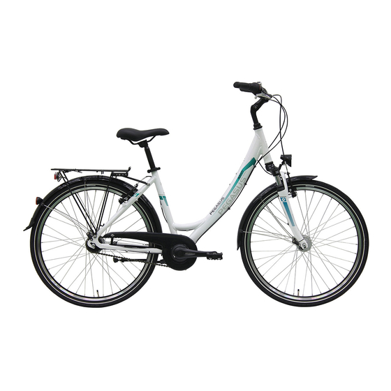
Description Description Overview Figure 2: Bicycle viewed from the right; Pegasus Solero SL used as example Front wheel Fork Front wheel guard Headlight Handlebars Stem Frame Seat post Saddle Pannier rack Rear light and reflector Rear wheel guard Rear wheel... -
Page 26: Handlebars
Description Handlebars Figure 3: Detailed view of bicycle from rider position, example 1 Figure 4: Detailed view of bicycle from left, example 2 Rear brake lever Headlight Bell Front brake lever Shifter Shifter Shift battery charging port Long shifter Brake lever Short shifter MY19-P073_1.0_09.11.2018... -
Page 27: Stem
Description 3.2.1 Stem The stem connects the fork to the handlebars. The sitting position of the rider is changed and optimised by changing the length and the angle of the stem. Figure 5: Detailed view of the stem, example of stem which can be set without tool Stem clamping lever Handlebars... -
Page 28: Wheel And Suspension
Description Wheel and suspension Figure 6: Components of the wheel, example of front wheel Tyre Suspension fork head with setting wheel Shock absorber Spoke Quick release Valve Fork end of the shock absorber 3.3.1 Valve Each wheel has a valve. It is used to fill the tyre with air. -
Page 29: Suspension
Description 3.3.2 Suspension Both forks and suspension forks are fitted in this model series. A suspension fork is based either on a steel spring or air suspension. Unlike a rigid fork, a suspension fork has two functions which improve floor contact and comfort: suspension and damping. -
Page 30: Suspension Fork Structure
Description Dampers which dampen compressive deflection movements, i.e. a compression load, are called compression dampers or compression dashpots. Dampers which dampen rebound deflection movements, i.e. a rebound load, are called rebound dampers or dashpots. 3.3.3 Suspension fork structure Figure 8: Example showing Suntour fork: The stem and handlebars are fastened to the fork shaft (1). -
Page 31: Brake System
Description Brake system The bicycle's brake system comprises either a hydraulic: • rim brake on the front and rear wheels, • disc brake on the front and rear wheels or • a rim brake on the front and rear wheels and an additional back-pedal brake. -
Page 32: Figure 10: Rim Brake Locking Lever, Closed (1) And Open (2)
Description The hydraulic rim brake features a locking lever Figure 10: Rim brake locking lever, closed (1) and open (2) The rim brake locking lever is not marked with any lettering. Only a specialist dealer may set the rim brake locking lever. -
Page 33: Figure 12: Brake System With A Back-Pedal Brake, Example
Description Brake disc Brake calliper with brake linings Handlebars with brake levers Front wheel brake disc Rear wheel brake disc On a bicycle with a disc brake, the brake disc is screwed permanently to the hub of the wheel. The brake lever is pulled to increase brake pressure. The brake fluid is used to transfer pressure through the brake lines to the cylinders in the brake calliper. - Page 34 Description Front wheel rim brake Pedal Back-pedal brake The back-pedal brake stops the movement of the rear wheel when the rider pedals in the opposite direction to the direction of travel. MY19-P073_1.0_09.11.2018...
-
Page 35: Drive System
Description Drive system The bicycle is driven by muscle power via the chain drive. The force which is applied by pedalling in the direction of travel, drives the front chain wheel. The chain transmits the force onto the rear chain wheel and then onto the rear wheel. -
Page 36: Technical Data
Technical data Technical data Bicycle Transportation temperature 5 °C–25 °C Storage temperature 5 °C–25 °C Operation temperature 5 °C–35 °C Working environment temperature 15 °C–25 °C Table 7: Bicycle technical data Tightening torque Axle nut tightening torque 35 Nm - 40 Nm Handlebars clamping screw maximum 5 Nm - 7 Nm tightening torque*... -
Page 37: Transportation, Storage And Assembly
Transportation, storage and assembly Transportation, storage and assembly Transportation O i l l e a k i f n o t r a n s p o r t s e c u r i n g d e v i c e CAUTION The brake securing device prevents the brakes from being applied accidentally during transport. -
Page 38: Using The Transport Securing System
Transportation, storage and assembly When transporting by car, you must use a suitable bicycle rack system. The specialist dealer will advise you on how to select a suitable rack system properly and how to use it safely. Transport the bicycle in a dry, clean place where it is protected from direct sunlight. -
Page 39: Storing
Transportation, storage and assembly Storing R i s k o f f i r e a n d e x p l o s i o n d u e t o h i g h CAUTION t e m p e r a t u r e s Excessively high temperatures will damage batteries. -
Page 40: Assembly
Transportation, storage and assembly Assembly Assemble the bicycle in a clean and dry environment. The working environment temperature should be between 15 °C and 25 °C. Working environment temperature 15 °C–25 °C Table 10: Working environment temperature 5.3.1 Required tools The following tools are required to assemble the bicycle:... -
Page 41: Scope Of Delivery
Transportation, storage and assembly 5.3.3 Scope of delivery The bicycle was completely assembled in the factory for test purposes and then dismantled for transportation. The bicycle is 95–98% pre-assembled. The scope of delivery includes: • the pre-assembled bicycle • the front wheel •... - Page 42 Transportation, storage and assembly Initial commissioning check list Mount the wheels, quick release and pedals. Re-adjust the quick release clamping force if necessary. Thoroughly degrease the brake discs in disc brakes or the brake sides and linings in rim brakes with brake cleaner or spirit. Place handlebars, stem and saddle in the functional position ...
-
Page 43: Mounting The Wheel With Screw-On Axle (15 Mm)
Transportation, storage and assembly 5.3.5 Mounting the wheel in the Suntour fork Alternative 5.3.5.1 Mounting the wheel with screw-on axle (15 mm) Alternative Insert the axle completely on the drive side. Figure 15: Fully inserting the axle Tighten the axle with a 5 mm hexagon socket spanner to 8–10 Nm. -
Page 44: Figure 17: Pushing The Quick Release Lever Into The Axle
Transportation, storage and assembly Insert the securing screw on the non-drive side. Figure 17: Pushing the quick release lever into the axle Tighten the securing screw with a 5 mm hexagon socket spanner to 5–6 Nm. The lever is mounted. Figure 18: Tightening the securing screw MY19-P073_1.0_09.11.2018... -
Page 45: Mounting The Wheel With Screw-On Axle (20 Mm)
Transportation, storage and assembly 5.3.5.2 Mounting the wheel with screw-on axle (20 mm) Alternative Insert the axle completely on the drive side. Figure 19: Tightening the inserted axle Tighten the securing clip with a 4 mm hexagon socket spanner to 7 Nm. Figure 20: Tightening the axle MY19-P073_1.0_09.11.2018... -
Page 46: Mounting The Wheel With A Quick Release Axle
Transportation, storage and assembly 5.3.5.3 Mounting the wheel with a quick release axle Alternative Crash caused by loose quick release axle CAUTION A faulty or incorrectly installed quick release axle may become caught in the brake disc and block the wheel. This will cause a crash. -
Page 47: Figure 21: Pushing The Axle Into The Hub
Transportation, storage and assembly Insert the axle into the hub on the drive side. Clamping version II. Figure 21: Pushing the axle into the hub Tighten the axle with the red handle. Figure 22: Tightening the axle MY19-P073_1.0_09.11.2018... -
Page 48: Figure 23: Pushing The Quick Release Lever Into The Axle
Transportation, storage and assembly Push the quick release lever into the axle. Figure 23: Pushing the quick release lever into the axle Reverse the quick release lever. The lever is secured. Figure 24: Securing the lever MY19-P073_1.0_09.11.2018... -
Page 49: Figure 25: Perfect Position For The Clamping Lever
Transportation, storage and assembly Check the position and clamping force of the quick release lever. The quick release lever must be flush with the lower housing. You must be able to see a slight impression on the palm of your hand when you close the quick release lever. -
Page 50: Mounting The Wheel With A Quick Release
Transportation, storage and assembly 5.3.6 Mounting the wheel with a quick release Alternative Crash caused by unfastened quick release CAUTION A faulty or incorrectly installed quick release may become caught in the brake disc and block the wheel. This will cause a crash. ... -
Page 51: Figure 27: Open And Closed Flange
Transportation, storage and assembly Before mounting, ensure that the quick release flange is extended. Open the lever completely. Figure 27: Open and closed flange Push in the quick release until you hear a clicking sound. Make sure that the flange is extended. Figure 28: Pushing the quick release in MY19-P073_1.0_09.11.2018... -
Page 52: Figure 29: Adjusting The Clamping
Transportation, storage and assembly Adjust the clamping with a half-open clamping lever until the flange reaches the fork end. Figure 29: Adjusting the clamping Fully close the quick release. Check the quick release to ensure it is firmly in place and adjust on the flange if necessary. -
Page 53: Checking The Stem And Handlebars
Transportation, storage and assembly 5.3.6.1 Checking the stem and handlebars Checking connections Stand in front of the bicycle to check whether the handlebars, stem and fork shaft are firmly attached to one another. Clamp the front wheel between your legs. Grasp the handlebar grips. Try to twist the handlebars towards the front wheel. -
Page 54: Sale Of The Bicycle
Transportation, storage and assembly Checking the headset backlash To check the handlebar headset backlash, close the quick release lever on the stem. Place the fingers of one hand on the upper headset cup, pull the front wheel brake with the other hand and try to push the bicycle backwards and forwards. -
Page 55: Before The First Ride
Before the first ride Before the first ride Crash caused by incorrectly adjusted torques CAUTION If a screw is fastened too tightly, it may break. If a screw is not fastened enough, it may loosen. This will result in a crash and injuries. ... -
Page 56: Determining The Seat Height
Before the first ride 6.1.2 Determining the seat height To determine the seat height safely, either push the bicycle near to a wall, so that you can lean on the wall to support yourself or ask another person to hold the bicycle for you. -
Page 57: Adjusting The Seat Height With Quick Release
Before the first ride 6.1.3 Adjusting the seat height with quick release Open the quick release on the seat post to change the seat height. To do so, pull the clamping lever away from the seat post. Figure 33: Seat post quick release (3) with clamping lever (5) and setting bolt (4) in the open position (1) and in the direction of the closed position (2) -
Page 58: Setting The Height-Adjustable Seat Post
Before the first ride Figure 34: Detailed view of the seat post – examples of the minimum insertion depth marking To close it, push the seat post clamping lever as far as it will go into the seat post. ... -
Page 59: Lowering The Saddle
Before the first ride 6.1.4.1 Lowering the saddle To lower the saddle, press your hand down on the saddle or sit on the saddle. Press the seat post activation lever and hold it down. Release the lever once you have reached the required height. -
Page 60: Adjusting The Handlebars
Before the first ride bring the saddle back. Move the saddle within its permitted displacement range only (marked on the saddle stay). 90° Figure 36: Knee cap perpendicular line Adjusting the handlebars The handlebars must only be adjusted while the bicycle is stationary. -
Page 61: Adjusting The Height Of The Handlebars
Before the first ride Adjusting the stem Crash caused by loose stem CAUTION Incorrectly fastened screws may come loose due to impact. The stem may no longer be firmly fixed in its position as a result. This will result in a crash and injuries. -
Page 62: Figure 37: Open (2) And Closed (1) Clamping Lever On The Stem
Before the first ride Figure 37: Open (2) and closed (1) clamping lever on the stem; by.schulz speedlifter used as an example 6.2.2 urning the handlebars to the side Alternative Crash caused by incorrectly set clamping force CAUTION Excessively high clamping force will damage the quick release and cause it to lose its function. -
Page 63: Checking The Clamping Force Of The Quick Releases
Before the first ride Figure 38: Pulling locking lever upwards; by.schulz speedlifter used as an example 6.2.2.1 Checking the clamping force of the quick releases Open and close the quick releases on the stem or the seat post. The clamping force is sufficient if the clamping lever can be moved easily from the open final position into the middle and has to be pressed with the fingers or base of the thumb from the middle... -
Page 64: Adjusting The Brake Lever
Before the first ride Adjusting the brake lever 6.3.1 Adjusting the pressure point on a Magura brake lever Brake failure due to incorrect setting WARNING If the pressure point is set with brakes where the brake lining and brake disc have reached their wear limit, the brakes may fail and cause an accident with injury. -
Page 65: Adjusting The Grip Distance
Before the first ride 6.3.2 Adjusting the grip distance Crash caused by incorrectly set grip distance WARNING If brake cylinders are set incorrectly or installed wrongly, the braking power may be lost at any time. This may cause you to fall from the bicycle and injure yourself. -
Page 66: Adjusting The Grip Distance On A Magura Brake Lever
Before the first ride 6.3.2.1 Adjusting the grip distance on a Magura brake lever Alternative Use a T25 TORX® wrench to turn the setting screw to adjust the grip distance. Turn the setting screw in the minus (–) direction. ... -
Page 67: Adjusting The Suspension
Before the first ride Adjusting the suspension Crash caused by incorrectly set suspension CAUTION If the suspension is adjusted incorrectly, the fork may become damaged, so that problems may occur when steering. This will result in a crash and injuries. ... -
Page 68: Adjusting The Negative Deflection
Before the first ride 6.4.1 Adjusting the negative deflection Negative deflection is compression caused by the rider's weight, including equipment (such as a backpack), sitting position and frame geometry. Each rider has a different weight and sitting position. Negative deflection depends on the rider's position and weight and should be between 15% and 30% of the maximum fork deflection, depending on the bicycle usage and preferences. -
Page 69: Adjusting The Air Suspension Fork Negative Deflection
Before the first ride Only adjust the negative deflection when the bicycle is stationary. The setting wheel may be located under a plastic cover on the suspension fork crown. Remove the plastic cover by pulling it off upwards. ... -
Page 70: Retracting Brake Linings
Before the first ride Adjusting the tyre pressure The tyre pressure determines the force required to press the fork together. If the tyre pressure is reduced, the fork slackens more and rebounds less. Figure 43: Screw caps in different designs ... -
Page 71: Operation
Operation Operation Crash caused by loose clothing CAUTION Laces, scarves and other loose items may become entangled in the spokes on the wheels and the chain drive. This may cause you to fall from the bicycle and injure yourself. Wear sturdy footwear and close-fitting clothing. Crash caused by soiling CAUTION Heavy soiling can impair the functions of the bicycle,... - Page 72 Operation Moisture penetrating at low temperatures may impair individual bicycle functions due to the open structural design. Always keep the bicycle dry and free from frost. If the bicycle is to be used at temperatures below 3 °C, the specialist dealer must carry out an inspection and prepare the bicycle for winter usage first.
-
Page 73: Before Each Ride
Operation Before each ride Crash caused by difficult-to-spot damage CAUTION If the bicycle topples over or you have a fall or an accident, there may be difficult-to-spot damage to components such as the brake system, quick releases or frame. This may cause you to fall from the bicycle and injure yourself. -
Page 74: Check List Before Each Ride
Operation Check list before each ride Check the bicycle before each ride. Do not use the bicycle if there are any anomalies. Check that the bicycle is complete. Check that the lighting, reflector and brake, for instance, are ... -
Page 75: Using The Kickstand
Operation Using the kickstand Crash caused by a lowered kickstand CAUTION The kickstand does not fold up automatically. There is a risk of crashing if riding with the kickstand lowered. Raise the kickstand completely before the ride. The heavy weight of the bicycle may cause the NOTICE kickstand to sink into soft ground and the bicycle may topple and crash over. -
Page 76: Using The Pannier Rack
Operation Using the pannier rack Crash caused by loaded pannier rack CAUTION The riding performance of the bicycle changes with a loaded pannier rack, in particular when steering and braking. This can lead to a loss of control. This may cause you to fall from the bicycle and injure yourself. - Page 77 Operation The maximum load bearing capacity is indicated on the NOTICE pannier rack. Never exceed the permitted total weight when packing the bicycle. Never exceed the maximum load bearing capacity of the pannier rack. Never modify the pannier rack. ...
-
Page 78: Gear Shift
Operation Gear shift The selection of the appropriate gear is a prerequisite for a physically comfortable ride and making sure that the electric drive system functions properly. The ideal pedalling frequency is between 70 and 80 revolutions per minute. It is advisable to stop pedalling briefly when changing gears. -
Page 79: Brake
Operation Brake Hydraulic fluid can be fatal if it is swallowed and DANGER penetrates into the respiratory system Hydraulic fluid may leak out after an accident or due to material fatigue. Hydraulic fluid can be fatal if swallowed and inhaled. First aid treatment ... - Page 80 Operation After contact with eyes Rinse eyes under flowing water for at least ten minutes with the lids open; also rinse under lids. Consult eye doctor if pain or discomfort continues. After ingestion Rinse out mouth with water Never induce vomiting! Risk of aspiration! ...
- Page 81 Operation Crash caused by brake failure WARNING Oil or lubricant on the brake disc in a disc brake or on the rim of a rim brake can cause the brake to fail completely. This may cause a crash with serious injuries as a consequence.
- Page 82 Operation Crash caused by incorrect use CAUTION Handling the brake improperly can lead to loss of control or crashes, which may result in injuries. Shift your body weight back and down as far as possible. Practise braking and emergency braking before the bicycle is used in public spaces.
-
Page 83: Using The Brake Lever
Operation The drive force of the motor is shut off during the ride as soon as the rider no longer pedals. The drive system does not switch off when braking. In order to achieve optimum braking results, do not pedal while braking. -
Page 84: Suspension And Damping
Operation Suspension and damping 7.7.1 Adjusting the compression of the Suntour fork Alternative The compression adjuster makes it possible to make quick adjustments to the suspension behaviour of the fork to suit changes in terrain. It is intended for adjustments made during the ride. Figure 46: Suntour compression adjuster with the OPEN (1) and LOCK (2) positions... -
Page 85: Maintenance
Maintenance Maintenance Cleaning check list Clean pedals after each ride Cleaning the suspension fork after each ride every Chain (mainly tarmacked road) 250–300 km Basic cleaning and preservation of all at least every six components months Clean and lubricate height-adjustable seat ... - Page 86 Maintenance Service check list Functional check on the suspension fork every 50 hours Suspension fork maintenance and every 100 hours or at dismantling least once a year Inspection by the specialist dealer every six months MY19-P073_1.0_09.11.2018...
-
Page 87: Cleaning And Servicing
Maintenance Cleaning and servicing The following servicing measures must be performed regularly. Servicing can be performed by the operator and rider. In case of any doubt, consult the specialist dealer. 8.1.1 After each ride 8.1.1.1 Cleaning the suspension fork Remove dirt and deposits on the stanchions and deflector seals with a damp cloth. -
Page 88: Basic Cleaning
Maintenance 8.1.2 Basic cleaning Crash caused by brake failure CAUTION The braking effect may be unusually poor temporarily after cleaning, servicing or repairing the bicycle. This may cause you to fall from the bicycle and injure yourself. Never apply care products or oil to the brake discs or brake linings, or the braking surfaces on the rims. -
Page 89: Cleaning The Frame
Maintenance 8.1.2.1 Cleaning the frame Soak dirt stains on the frame with dish-washing detergent if the dirt is thick and ingrained. After leaving it to soak for a time, remove the dirt and mud with a sponge, brush and toothbrush. ... -
Page 90: Cleaning The Drive Elements
Maintenance 8.1.2.5 Cleaning the drive elements Spray the cassette, the chain wheels and the front derailleur with a degreasing agent. Clean coarse dirt with a brush after soaking for a short time. Wash down all parts with dish-washing detergent and a toothbrush. -
Page 91: Cleaning The Brake
Maintenance 8.1.2.7 Cleaning the brake Brake failure due to water penetration WARNING The brake seals are unable to withstand high pressures. Damaged brakes can fail and cause an accident with injury. Never clean the bicycle with a high-pressure water device or compressed air. -
Page 92: Servicing The Fork
Maintenance 8.1.3.3 Servicing the fork Treat the dust seals with fork oil 8.1.3.4 Servicing the drive elements Spray the cassette, the chain wheels and the front derailleur with a degreasing agent. Clean coarse dirt with a brush after soaking for a short time. -
Page 93: Service
Maintenance Service Crash and falling caused by unintentional activation CAUTION There is a risk of injury if the drive system is activated unintentionally. Remove the battery before inspection. Crash caused by material fatigue CAUTION If the service life of a component has expired, the component may suddenly fail. - Page 94 Maintenance The specialist dealer will fully inspect the interior and exterior of the rear frame damper, overhaul the rear frame damper, replace all air seals of air forks, overhaul the air suspension, change the oil and replace the dust wipers. ...
-
Page 95: Adjusting And Repairing
Maintenance Adjusting and repairing Crash and falling caused by unintentional CAUTION activation There is a risk of injury if the drive system is activated unintentionally. Remove the battery before inspection. 8.3.1 Use original parts and lubricants only The individual parts of the bicycle have been selected carefully and to matched to each other. -
Page 96: Axle With Quick Release
Maintenance 8.3.2 Axle with quick release Crash caused by unfastened quick release CAUTION A faulty or incorrectly installed quick release may become caught in the brake disc and block the wheel. This will cause a crash. Install the front wheel quick release lever on the opposite side to the brake disc. -
Page 97: Checking The Quick Release
Maintenance 8.3.2.1 Checking the quick release Check the position and clamping force of the quick release lever. The quick release lever must be flush with the lower housing. You must be able to see a slight impression on the palm of your hand when you close the quick release lever. -
Page 98: Adjusting The Tyre Pressure
Maintenance 8.3.3 Adjusting the tyre pressure 8.3.3.1 Dunlop valve The tyre pressure cannot be measured on the simple Dunlop valve. The tyre pressure is therefore measured in the filling hose when pumping slowly with the bicycle pump. It is recommendable to use a bicycle pump with a pressure gauge. -
Page 99: Presta Valve
Maintenance 8.3.3.2 Presta valve It is recommendable to use a bicycle pump with a pressure gauge. The operating instructions for the bicycle pump must be adhered to. Unscrew and remove the valve cap. Open the knurled nut around four turns. ... -
Page 100: Schrader Valve
Maintenance 8.3.3.3 Schrader valve It is recommendable to use a bicycle pump with a pressure gauge. The operating instructions for the bicycle pump must be adhered to. Unscrew and remove the valve cap. Connect the bicycle pump. ... -
Page 101: Adjusting The Gear Shift
Maintenance 8.3.4 Adjusting the gear shift If you cannot select the gears effortlessly, you will need to adjust the setting for the shift cable tension. Carefully pull the adjusting sleeve away from the shifter housing, turning it as you do so. ... -
Page 102: Cable-Operated Gear Shift, Dual-Cable
Maintenance 8.3.4.2 Cable-operated gear shift, dual-cable Alternative For a smooth gear shift, set the adjusting sleeves underneath the chain stay on the frame. The shift cable has around 1 mm play when it is pulled out gently. Figure 53: Adjusting sleeves (2) on two alternative versions (A and B) of a dual-cable cable-operated gear shift on the chain stay (1) MY19-P073_1.0_09.11.2018... -
Page 103: Cable-Operated Twist Grip, Dual-Cable
Maintenance 8.3.4.3 Cable-operated twist grip, dual-cable Alternative For a smooth gear shift, set the adjusting sleeves on the shifter housing. There is noticeable play of around 2–5 mm (1/2 gear) when twisting the twist grip. Figure 54: Twist grip with adjusting sleeves (1) and play of the gear shift (2) MY19-P073_1.0_09.11.2018... -
Page 104: Offsetting The Brake Lining Wear
Maintenance 8.3.5 Offsetting the brake lining wear 8.3.5.1 Hydraulically operated rim brake Alternative The setting bolt on the brake lever of the hydraulic rim brake is used to offset the brake lining wear. If the profile of the brake linings has a remaining depth of just 1 mm, the brake linings need to be replaced. -
Page 105: Replacing The Lighting
Maintenance 8.3.6 Replacing the lighting Alternatively a 3 watt or 1.5 watt lighting system can be installed. Only use components of the respective power class for replacement. 8.3.7 Setting the headlight The headlight must be set, so that its light beam meets the road 10 m in front of the bicycle. -
Page 106: Accessories
Accessories Accessories For bicycles without a kickstand we recommend a parking stand into which either the front or rear wheel can be inserted securely. The following accessories are recommended: Description Article number Rear wheel basket, system 051-20603 component* Bicycle box, system component* 080-40947 Parking stand universal stand XX-TWO14B... -
Page 107: Child Seat
Accessories 8.4.1 Child seat Crash caused by incorrect child seat WARNING Neither the pannier rack nor the bicycle down tube are suitable for child seats and may break. Such an incorrect position may cause a crash with serious injuries for the rider and the child. ... -
Page 108: Bicycle Trailer
Accessories The specialist dealer will advise on choosing a suitable child seat system for the child and the bicycle. The specialist dealer must mount the child seat the first time to ensure that it is safely fitted. When installing a child seat, the specialist dealer makes sure that the fastening mechanism for the seat is suitable for the bicycle and that all components are installed and firmly fastened. -
Page 109: Pannier Rack
Accessories Figure 56: Trailer sign The specialist dealer will advise on choosing a suitable trailer system for the bicycle. The specialist dealer must install the trailer the first time to ensure that it is safely fitted. 8.4.3 Pannier rack The specialist dealer will advise on choosing a suitable pannier rack. -
Page 110: Recycling And Disposal
Recycling and disposal Recycling and disposal The bicycle is made of valuable materials. You must dispose of and recycle them separately from domestic waste in compliance with the applicable statutory regulations. Sorted waste collection and recycling saves on raw material reserves and ensures that all the regulations for health and environmental protection are met when the product and/or the battery are recycled. - Page 111 Table of figures Table of figures Figure 1: Type plate, example, 15 Figure 2: Bicycle viewed from the right; Pegasus Solero SL used as example, 25 Figure 3: Detailed view of bicycle from rider position, example 1, 26 Figure 4:...
- Page 112 Table of figures Figure 31: Horizontal saddle tilt, 55 Figure 32: Optimal saddle height, 56 Figure 33: Seat post quick release (3) with clamping lever (5) and setting bolt (4) in the open position (1) and in the direction of the closed position (2), 57 Figure 34: Detailed view of the seat post –...
- Page 113 Table of figures Figure 55: Brake lever (1) of the hydraulically operated rim brake with setting bolt (2), 104 Figure 56: Trailer sign, 109 MY19-P073_1.0_09.11.2018...
- Page 114 List of tables List of tables Table 1: Meanings of the signal words, 11 Table 2: Safety markings on the product, 12 Table 3: Area of use, 13 Table 4: Bicycle type, 13 Table 5: Conventions, 14 Table 6: Identification number of the operating instructions, 16 Table 7: Bicycle technical data, 36 Table 8:...
-
Page 115: Subject Index
Index Subject index Rim brake locking lever 32 Alternative equipment, 14 Fork, 28 Rim, 28 Alternative version, 14 - adjusting tyre pressure, - replacing, 105 Area of use, 13 Roller brake, Fork end, 28 -braking, 83 structure, 30 Back-pedal brake, 31, 32, 33 Frame number, 3 -braking, 83 Saddle,... - Page 116 Text and images: ZEG Zweirad-Einkaufs-Genossenschaft eG Longericher Straße 2 50739 Köln, Germany Translation: Tanner Translations GmbH+Co Markenstraße 7 40227 Düsseldorf, Germany Operating instructions: MY19-P073_1.0_09.11.2018...
- Page 117 www.zeg.de ZEG Zweirad-Einkaufs-Genossenschaft eG Longericher Straße 2 50739 Köln, Germany Tel.: +49 221 17959 0 YOUR ZEG SPECIALIST DEALER...
Need help?
Do you have a question about the Avanti and is the answer not in the manual?
Questions and answers