Table of Contents
Advertisement
Quick Links
Advertisement
Table of Contents

Related Manuals for Lacunza INCA80


Summary of Contents for Lacunza INCA80
- Page 1 Inca 80-100 C/V Instruction Book...
-
Page 2: Table Of Contents
PRESENTATION OF THE APPLIANCE Lacunza congratulates you on your choice. Certified under ISO 9001, Lacunza guarantees the quality of its appliances and undertakes to meet the needs of its customers. Confident of the know-how afforded by more than 50 years’ experience, Lacunza uses advanced technologies in the design and manufacture of its entire range of appliances. - Page 3 PRESENTATION OF THE APPLIANCE 3.8. Opening the door ............................19 3.9. Electrical system............................19 MAINTENANCE AND IMPORTANT ADVICE ..................21 4.1. Maintenance of the appliance ........................21 4.1.1. Firebox ................................... 21 4.1.2. Inside the appliance ............................... 21 4.1.3. Flue socket ................................21 4.1.4.
-
Page 4: Presentation Of The Appliance
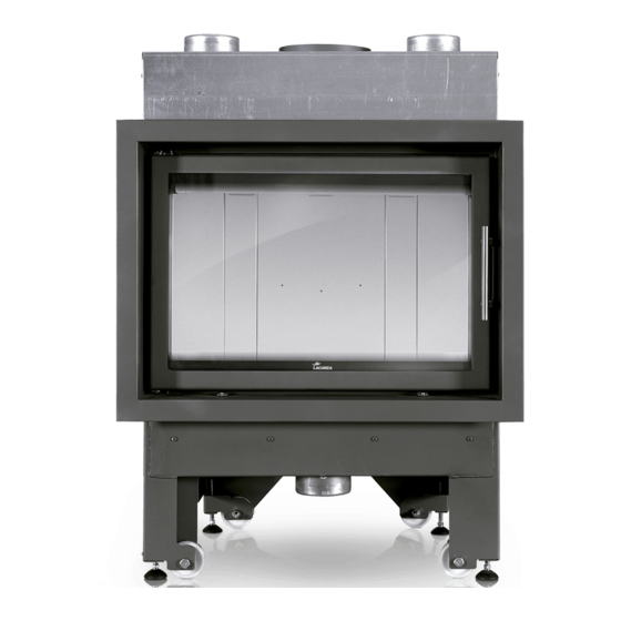
PRESENTATION OF THE APPLIANCE PRESENTATION OF THE APPLIANCE For optimum operation of the appliance, we advise you to read this manual carefully before switching on the appliance for the first time. In case of problems or concerns, we urge you to contact your dealer, who will cooperate with you. - Page 5 PRESENTATION OF THE APPLIANCE with the appliance (deterioration, shorter useful life, etc.) which are not covered by the Lacunza warranty. Figure No.1 - Dimensions of the INCA 80 appliance in mm...
- Page 6 PRESENTATION OF THE APPLIANCE Figure No.2 - Dimensions of the INCA 100 appliance in mm...
-
Page 7: Instructions For The Installer
P ≤ 10kW fixtures, etc.). 10 < P ≤ 15 Lacunza’s liability is limited to the 15 < P ≤ 20 supply of the material and does not include 20 < P ≤ 25 installation of the appliance. -
Page 8: Location Of The Appliance In The Room
INSTRUCTIONS FOR THE INSTALLER pressure and it is necessary to install a non- material is not designed to withstand high closable outside-air inlet with a section of temperatures. at least 90 cm². 2.3.3. Checks before lighting for the first 2.2.2. Location of the appliance in the time room •... - Page 9 INSTRUCTIONS FOR THE INSTALLER Figure No.5 - Exterior diagram of the casing Figure No.4 - Interior diagram of the casing order enable suitable circulation and correct operation, the Key to casing diagram: casing must have a fresh-air inlet with a 1 Ceiling minimum section of 1,000cm beneath the...
-
Page 10: Connection To The Flue
INSTRUCTIONS FOR THE INSTALLER • The air ducts must always be heat non-central-heating appliances (without back boiler), Lacunza does not insulated and smooth inside (not recommend enveloping the outside of corrugated). appliances with insulation. • The pipes must always have an upward slant to facilitate movement by ¡Warning!: The installer must fit the... -
Page 11: Piping Air To The Firebox
INSTRUCTIONS FOR THE INSTALLER 2.3.8. Piping air to the firebox OPTION A: Combustion-air intake from inside the room and hot-air output by On this model, it is possible to pipe air natural convection (without fan). to the appliance for combustion straight from outdoors. - Page 12 INSTRUCTIONS FOR THE INSTALLER OPTION D: Combustion-air intake from outside the room and hot-air output by forced convection (with fan). The installation system for this option is the same as that of the previous option, but also involves leading the hot-air output from the nozzles on top to the hot-air output grilles or to other adjoining rooms via piping with a diameter of 120mm.
-
Page 13: Exterior Frame. Removal And Assembly
INSTRUCTIONS FOR THE INSTALLER sides of the casing, which draw air in from 2.3.10. Fan-potentiometer connection the room the appliance is fitted in) (only for models C/V) because they are separate air circuits. ITACA-INCA c/v models (the models with fans) are prepared for connection on the potentiometer supplied. -
Page 14: Chimney Flue
WARNING: the operating temperature the appliance over its entire length in order of the potentiometer supplied by Lacunza to ensure correct operation. on ITACA C/V models (with fan) is from 0 to 40ºC. -
Page 15: Chimney Crown
INSTRUCTIONS FOR THE INSTALLER It must be possible to clean the entire Figure No.13 - Distances between chimney crown and roof ridge flue, no sections being left inaccessible for cleaning purposes. The chimney crown must clear the 2.4.2. Chimney crown highest point of any neighbouring building or obstacle located within a 10m radius of The upper end of the chimney must... -
Page 16: Instructions Of Use
INSTRUCTIONS OF USE • Resinous wood may mean that the INSTRUCTIONS OF USE appliance and the flue need to be cleaned more often. The manufacturer accepts no liability whatsoever for damage caused to parts as Non-permitted fuels: a result of the improper use of non- •... -
Page 17: Description Of The Parts Of The Appliance
INSTRUCTIONS OF USE 3.2. Description of the parts of the appliance 3.2.1. Operating components Figure No.17 - Operating components on the appliance • A: Primary air intake A1 open (move towards the + symbol) A2 closed (move towards the - symbol) •... -
Page 18: Loading Fuel
INSTRUCTIONS OF USE • The first time the appliance is lit, Vermiculite is a fragile material and may crack if knocked. the fire should be gentle to allow the parts of the appliance to dilate and dry. 3.5. Operation Important: The first time it is lit up, the The appliance should be operated with appliance may give off smoke and strange the door closed. -
Page 19: Removing Ash
INSTRUCTIONS OF USE make up the appliance. Do not be alarmed by noises of this kind. In order to obtain maximum output, open all the air intakes to the firebox and in order to obtain minimum output, tend towards closing them. For normal use, we recommend you close the Primary Intake and leave the Secondary and Double Combustion Intakes open. -
Page 20: Opening The Door
INSTRUCTIONS OF USE 3.8. Opening the door Figure No.20 - Dismantling the lower Inca deflector Figure No.22 - Opening the door Soot falling from the flue may build up on the deflector. 3.9. Electrical system Then remove the second deflector by Forced convetion. - Page 21 INSTRUCTIONS OF USE Potentiometer operation: By means of its rotating lever, the potentiometer controls the flow of hot-air output from the appliance in two ways: • Automatic mode: The fan automatically starts working at the set speed via the thermostat. When a fire has been lit in the firebox and the thermostat reaches a temperature of approximately 50ºC, the fan starts working...
-
Page 22: Maintenance And Important Advice
It must be cleaned as often as required. Lacunza-authorised replacement parts be How often it is cleaned depends on how used. Lacunza accepts no liability for any much the appliance is used and the type of modification to the product which it has fuel employed. -
Page 23: Troubleshooting
TROUBLESHOOTING TROUBLESHOOTING This symbol means that a qualified professional should be called to perform the operation. Problem Probable causes Solution Use hard woods, cut at least 2 years ago and stored in a Green or damp wood sheltered, ventilated place Use crumpled paper or firelighters and dry wood chips to light The logs are too large the fire. -
Page 24: Basic Breakdowns
BASIC BREAKDOWNS BASIC BREAKDOWNS... - Page 25 BASIC BREAKDOWNS...
-
Page 26: Declaration Of Performance
DECLARATION OF PERFORMANCE DECLARATION OF PERFORMANCE... - Page 27 DECLARATION OF PERFORMANCE...
- Page 28 DECLARATION OF PERFORMANCE...
- Page 29 DECLARATION OF PERFORMANCE...
-
Page 30: Ce Mark
CE MARK CE MARK... - Page 31 CE MARK...
- Page 33 LACUNZA KALOR GROUP S.A.L Pol. Ind. Ibarrea s/n 31800 Alsasua (Navarra) Spain Tel.: (00 34) 948 56 35 11 Fax.: (00 34) 948 56 35 05 e-mail: comercial@lacunza.net Website: www.lacunza.net EDITION: 02...
Need help?
Do you have a question about the INCA80 and is the answer not in the manual?
Questions and answers