
Related Manuals for Vertilon SIB71256

Summary of Contents for Vertilon SIB71256
- Page 1 User Guide SIB71256 256 Channel MAPMT Interface Board Hamamatsu H13700 Series Vertilon Corporation, 66 Tadmuck Road, Westford, MA 01886 Tel: (978) 692-7070 Fax: (978) 692-7010 www.vertilon.com...
- Page 3 Vertilon reserves the right to change this product without prior notice. No responsibility is assumed by Vertilon for any infringements of patents or other rights of third parties which may result from its use. No license is granted by implication or otherwise under the patent and proprietary information rights of Vertilon Corporation.
- Page 4 SIB17256 Sensor Interface Board for Hamamatsu H13700 MAPMT - 4 - Vertilon Corporation, 66 Tadmuck Road, Westford, MA 01886 Tel: (978) 692-7070 www.vertilon.com...
-
Page 5: Table Of Contents
Photomultiplier Tube Anode Circuit...................... 11 Anger Logic ............................. 12 Last Dynode Output ..........................13 Gain Switches ............................13 Top and Bottom Views ........................... 14 Mechanical Information .......................... 15 - 5 - Vertilon Corporation, 66 Tadmuck Road, Westford, MA 01886 Tel: (978) 692-7070 www.vertilon.com... - Page 6 Figure 6: Dynode Preamplifier Response ....................13 Figure 7: Gain Switch Positions ....................... 13 Figure 8: Top and Bottom Views ......................14 Figure 9: SIB71256 Printed Circuit Board Dimensions ................15 Figure 10: SIB71256 3D View ......................... 15 - 6 -...
- Page 7 User Guide General Safety Precautions Use Proper Power Source The SIB71256 is powered with a +12V power source. Use with any other power source may result in damage to the product. Operate Inputs within Specified Range To avoid electric shock, fire hazard, or damage to the product, do not apply a voltage to any input outside of its specified range.
-
Page 8: Product Overview
PMT’s 256 anode signals and last dynode output to the board. The high voltage bias to the PMT is supplied separately on its own cable and thus never reaches the SIB71256. The anode signals are routed to an on-board resistive anger logic circuit that generates four anger signal outputs. -
Page 9: Typical Setup
Typical Setup A typical setup using a SIB71256 is shown below. The Hamamatsu H13700 MAPMT is mounted to the SIB71256 and positioned to detect incoming light from a scintillator crystal or optical assembly. The four anger logic outputs from the SIB71256 connect to four inputs on a PhotoniQ IQSP418 / IQSP518 multichannel PMT data acquisition system. -
Page 10: Specifications
Into 50 ohms Output Impedance POWER Supply Voltage Vsupply Supply Current Isupply DIMENSIONS Width Length Thickness 1.57 (printed circuit board only) Table 1: Specifications - 10 - Vertilon Corporation, 66 Tadmuck Road, Westford, MA 01886 Tel: (978) 692-7070 www.vertilon.com... -
Page 11: Photomultiplier Tube Anode Circuit
Photomultiplier Tube Anode Circuit The 256 anode signals (P1 – P256) from the H13700 MAPMT are routed directly on the SIB71256 to the resistive anger logic circuit shown in the figure below. Each anger signal is amplified by high speed inverting preamplifiers and output on the SMB connectors on the four corners of the printed circuit board. -
Page 12: Anger Logic
SIB17256 Sensor Interface Board for Hamamatsu H13700 MAPMT Anger Logic Position information is obtained from the SIB71256 anger logic circuit using the formulas below to determine the X and Y coordinates. = (V – V – V ) / (V = (V –... -
Page 13: Last Dynode Output
Last Dynode Output The last dynode of the H13700 is directly connected on the SIB71256 to a non-inverting preamplifier whose output is available on an SMB connector. A miniature rotary switch allows the user to select between one of two gain settings. The last dynode output is typically used with an external discriminator for generating a trigger signal to data acquisition electronics or a time-to-digital converter (TDC) for determining time of arrival or coincidence detection. -
Page 14: Top And Bottom Views
+12V Power Input (Micro B USB 2.0) 10. Gain Adjust G241 11. Anger SMB Output V241 12. H13700 Mating Connector (SIG1) 13. H13700 Mating Connector (SIG2) - 14 - Vertilon Corporation, 66 Tadmuck Road, Westford, MA 01886 Tel: (978) 692-7070 www.vertilon.com... -
Page 15: Mechanical Information
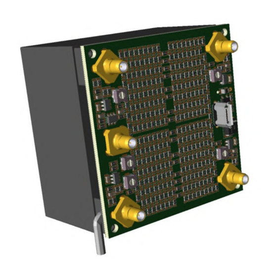
User Guide Mechanical Information Figure 9: SIB71256 Printed Circuit Board Dimensions Figure 10: SIB71256 3D View - 15 - Vertilon Corporation, 66 Tadmuck Road, Westford, MA 01886 Tel: (978) 692-7070 www.vertilon.com... - Page 16 Vertilon reserves the right to change this product without prior notice. No responsibility is assumed by Vertilon for any infringements of patents or other rights of third parties which may result from its use.
Need help?
Do you have a question about the SIB71256 and is the answer not in the manual?
Questions and answers