
Related Manuals for Stealth Products IC12F-1


Summary of Contents for Stealth Products IC12F-1
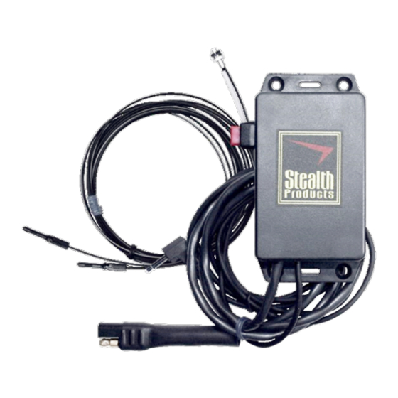
- Page 1 Alternative Drive Controls Fiber Optics Owner’s Manual - Maintenance Guide IC12F-1, IC24F-1, IDH503, IDHF510-1 Fiber Optic Switches...
-
Page 2: Table Of Contents
Table of Contents Customer Satisfaction .............i Important Information............ii-iii Warranty ...................ii Supplier Reference................ii Warning Labels................iii Limited Liability................iii Testing ....................iii Design and Function ...............1 Intended Use.................. 1 Specifications................. 1 Installation Instructions ............. 2-5 Installation Notes ................. 2 Mounting the Amplifier Box ............ 3 Power Supply ................. -
Page 3: Customer Satisfaction
Customer Satisfaction Stealth Products is committed to 100% customer satisfaction. Your complete satisfaction is important to us. Please contact us with feedback or suggestions to help us improve the quality and usability of our products. You may reach us at:... -
Page 4: Important Information
Warranty Our products are designed, manufactured, and produced to the highest of standards. If any defect in material or workmanship is found, Stealth Products will repair or replace the product at our discretion. Any implied warranty, including the implied warranties of merchantability and fitness for a particular purpose, shall not extend beyond the duration of this warranty. -
Page 5: Warning Labels
Stealth Products does not hold responsibility for final integration of final assembly of product to end user. Stealth Products is not liable for user death or injury. Testing Initial setup and driving should be done in an open area free of obstacles until the user is fully capable of driving safely. -
Page 6: Design And Function
Design and Function Intended Use The Fiber Optic is a small sensor that can easily be situated in confined spaces, individually, or in groups to create an array of switch sensors. It can be powered by the i-Connect system or the i-Drive interface, does not conduct electricity, or require physical contact to operate, and can be connected to virtually any available switch site. -
Page 7: Installation Instructions
Installation Instructions Installation Notes ▪ To bend the cable, we recommend a bend radius that is at least 6.6mm (.26 in). 20mm min. ✓ ✗ Amplifier Unit Fiber Unit 20mm min. ▪ Do not bend the edge of the fiber units closest to the tip and sensor. ▪... -
Page 8: Mounting The Amplifier Box
Installation Instructions Mounting the Amplifier Box ▪ The amplifier box should be mounted in a secure location where it will not be damaged. ▪ Mount the amplifier box using the mounting tabs on the edges of the box or by applying hook and loop material or another suitable form of removable adhesive. -
Page 9: Power Supply
Installation Instructions Power Supply The i-Connect version of Fiber Optics (IC12F-1 and IC24F-1) will require an appropriate version of the i-Connect power source. For more information, see the ICPS user manual (Available at https://stlpro.site/stealth-docs, search: ICPS) The i-Drive compatible version (IDH503 & IDHF510-1) will be powered by the i-Drive. -
Page 10: Locking The Cable In The Amplifier
Installation Instructions Locking the Cable in the Amplifier Open the lock lever by releasing it away from the fiber cable receiving holes. Insert the fiber cable into the receiver hole until it bottoms out. Do not force it past this point. Close the lock lever by flipping it toward the receiver holes. -
Page 11: Programming Instructions
Programming Instructions Layout NOTICE All of Stealth's Fiber Optics utilize the same amplifier. • Threshold Level -- Numbers displayed in Green. This indicates the level that must be achieved to cause a successful activation. • Incident Light Level -- Numbers displayed in Red. This indicates the level at which the Fiber Optic is currently sensing a reflection, i.e. -
Page 12: Tuning
Tuning Tuning Automatic Tuning Automatic Tuning will capture the capabilities of the end user. This will automatically assign a threshold level based on light levels during tuning. Press the Tune button once while breaking the beam. The display will read St 1Pnt. Press the Tune button once again with nothing breaking the beam. -
Page 13: Additional Features
Tuning Additional Features Light On / Dark On A single press of the L/D button will swap between the Light On and Dark On modes. ▪ Light On: User must break the beam to activate, much like a normally open switch. ▪... -
Page 14: First-Time Use
First Time Use Dealer Assistance During first time use by the client, it is advised that the dealer or service technician assists and explains the configuration to the customer (the user and/or the attendant). If needed the dealer can make final adjustments. User Testing It is important that the customer is fully aware of the installation and what/ how the product can be adjusted. -
Page 15: Maintenance
Maintenance Cleaning Periodically ensure the fiber optic sensor is free and clear of foreign debris. To clean: ▪ Gently wipe off with a dry cloth, or blow off with compressed air. ▪ Do not use thinners or other organic solvents. ▪... - Page 16 © 2021, Stealth Products, LLC Stealth Products, LLC · info@stealthproducts.com · www.stealthproducts.com (800) 965-9229 | (512) 715-9995 | 104 John Kelly Drive, Burnet, TX 78611 P140D508R2 Fiber Op�c Owners Manual.afpub Jul 15, 2021...
Need help?
Do you have a question about the IC12F-1 and is the answer not in the manual?
Questions and answers