Table of Contents
Advertisement
Quick Links
Advertisement
Table of Contents

Related Manuals for Stealth Products mo-Vis


Summary of Contents for Stealth Products mo-Vis
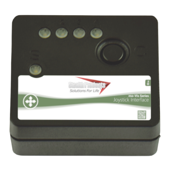
- Page 1 Multi Switch Owner's Manual for the mo-Vis Multi Switch...
-
Page 2: Customer Satisfaction
Customer Satisfaction Stealth Products strives for 100% customer satisfaction. Your complete satisfaction is important. Please contact us with feedback or to suggest changes that may help us improve the quality and usability of our products. You may reach us at:... - Page 3 Important Information Important Information All persons responsible for fitting, adjustment, and daily use of the devices discussed in these instructions must be familiar with and understand all safety aspects of the devices mentioned. In order for our products to be used successfully, you must: •...
-
Page 4: Introduction
Ordering Documentation You can download additional copies of this user manual by accessing the Stealth Products website (https://stlpro.site/stealth-docs) and searching "mo-Vis Multi Switch Owners Manual" in the search bar at the top of the page. -
Page 5: Warranty
Stealth Products, LLC. Any lack or alteration of serial number, where applicable, will automatically void this warranty. Stealth Products, LLC is liable for replacement parts only. Stealth Products, LLC is not liable for any incurred labor costs. -
Page 6: Table Of Contents
9.0 Technical Data ........................4-13 9.1 USB Power Supply ......................4 9.2 Input............................4 9.3 Output............................ 4 9.4 mo-Vis Configurator Software..................5 9.5 Output Operation Mode Selection ................5 9.6 Troubleshooting .......................10 9.7 Technical Dimensions and Specifications ...............13 10.0 Installation Instructions......................14 10.1 Preparations ........................14... -
Page 7: Warning Labels
Limited Liability Stealth Products, LLC accepts no liability for personal injury or damage to property that may arise from the failure of the user or other persons to follow the recommendations, warnings, and instructions in this manual. -
Page 8: Design And Function
The Multi Switch is also available as part of a package which includes proximity sensors. The sensors can be used as input devices and require no force to activate. The addition of mo-Vis proximity sensors increases the level of autonomy afforded the chair user. -
Page 9: Parts And Accessories
Product Description Multi Switch Unit USB to Micro USB Connector Cable For proximity sensor input, only mo-Vis proximity sensors (sold separately) are compatible with the Multi Switch. These are: Product Description Multi Switch Proximity Sensor (12mm) Multi Switch Proximity Sensor (24mm) Optional: Splitter Cable The 3.5mm stereo to 3.5mm... -
Page 10: Mounting The Multi Switch
Parts and Accessories Mounting the Multi Switch Its exceedingly small size grants the Multi Switch nearly unlimited mounting options. The use of hook-and-loop adhesive patches is recommended when mounting the switch. (Note: Hook-and-loop adhesive patches are not included with the Multi-Switch.) Only install this product on wheelchairs onto which NOTICE the manufacturer allows the installation of third-party parts. -
Page 11: Technical Data
Accordingly, proper device functionality is not guaranteed with any power source. Contact your dealer or mo-Vis for more information and for assistance with choosing the correct power source for the Multi Switch. A ground loop can be introduced into the connection if the USB port and the input jack are plugged into circuits powered by the same battery. -
Page 12: Mo-Vis Configurator Software
With Dealer-level software access, you will be able to configure a number of parameters for the Multi Switch. - Dealer-level access requires a password. To obtain a password for the software, call Stealth Products at (512) 715-9995 or toll-free at (800) 965-9229 and speak to a customer service representative. - Page 13 Technical Data Mode Select Click Mode: To generate one or more short clicks, quickly open and close (activate and deactivate) the input. (The period between the clicks has to be shorter than the 'Action Delay' time.) After the clicks are input, - The output will be closed for a set time (depending on the output's 'Close Time' setting), or - the selected output will remain locked until released (depending on the output's 'Lock' setting).
- Page 14 Technical Data - The output will remain closed as long as the input is closed, or - the output will remain locked until it is manually deselected (depending on the output's 'Lock' setting). (Note: If too much time elapses without selecting and activating an output, the selection process will stop and no output will be activated.
- Page 15 Technical Data Momentary/Timed or Switch Mode Momentary/Timed: - The output will remain closed as long as the input is closed, or - the output will be closed for a set time. Switched: - the output will toggle between open and closed. This is useful to switch something on continuously. Lock Mode 'Lock Mode' is designed to allow the user to control and activate a device for longer periods of time (e.g., with a communication or environmental device).
- Page 16 Technical Data Calibration Mode Auto: The system will make automatic adjustments over time. (Note: This is only a usable setting for situations in which the user of the device is able to maintain a distance of at least 30mm (12") from the sensor when he/she is not operating it.) Manual: Have the user determine at what point he/she would like the input to be considered open/activated.
-
Page 17: Troubleshooting
- Update Software - Replace PCB Coding error Should a problem persist after corrective action, please contact your local dealer or mo-Vis service engineer. Error Codes: The Multi Switch maintains a fault log with fault counters. Each time a specific fault occurs, its counter will be incremented by one. - Page 18 Technical Data Parameter: Min.: Max.: Default/Options: Description: Select by Click Start Scan See 9.5 Output Operation Mode Selection Select Mode Hold and Scan (Mode Select, p. 6) Select Timed Click Continuous Scan Active The number of outputs used Outputs (If set to '1', the switch will never enter Select mode) Calibration Auto See 9.5 Output Operation Mode Selection...
- Page 19 Technical Data OUTPUT SETTINGS: Parameter: Min.: Max.: Default/Options: Description: Output will remain closed at least as long as Momentary/Timed the Close Time, or longer. Mode Switched Output will toggle between open and closed Time (in ms) output will remain closed Close Time 60000 (timed output only)
-
Page 20: Technical Dimensions And Specifications
- MicroUSB = 5V Power Consumption: - 14 mA Input: - Mechanical switch (Closed = 200kOhm max.; Open = 150kOhm min.) - mo-Vis proximity sensor (12mm or 24mm) Output: - Max. = 60V (75mA) Sensor Cable Length: - 120cm (3.93 ft.) -
Page 21: Installation Instructions
Installation Instructions 10.0 Preparations 10.1 Only a qualified service technician should install the Multi Switch and its accessories. An incorrect installation of the Multi Switch and its accessories may cause WARNING damage to the hardware and/or injury to the user. Tools 10.2 Use the proper tools to install and adjust the Multi Switch to the desired position for the user. -
Page 22: First Time Use
• Is every function accessed by the switch functioning providing the least effort for the user? 5. If needed, adjust the Multi-Switch (with the Mo-Vis Configurator software) and retest until there's optimal position and functioning. 6. Explain to the customer possible problems and how to address them (see Troubleshooting) Conditions of Use 11.3... -
Page 23: Maintenance
Maintenance 12.0 Maintenance 12.1 These care and guideline instructions will keep the hardware in good condition for a longer period of time and prevent damage. • Check and re-tighten all fasteners on a regular basis. • Repair or replace parts as needed. •... - Page 24 © 2021, Stealth Products, LLC Stealth Products, LLC · info@stealthproducts.com · www.stealthproducts.com (800) 965-9229 | (512) 715-9995 | 104 John Kelly Drive, Burnet, TX 78611 P120D657 -- mo-Vis Multi Switch Owners Manual.pdf Jan 20, 2021...
Need help?
Do you have a question about the mo-Vis and is the answer not in the manual?
Questions and answers