Advertisement
Available languages
Available languages
Advertisement
Table of Contents

Related Manuals for Sav SAV 876.10

Summary of Contents for Sav SAV 876.10
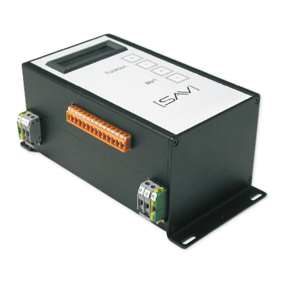
- Page 1 B E D I E N U N G S A N L E I T U N G O P E R AT I N G I N S T R U C T I O N S SAV 876.10 für elektronische Umpolsteuer- geräte...
-
Page 3: Table Of Contents
Garantiebedingungen Copyright: Nachdruck - auch auszugsweise - nur mit ausdrücklicher Genehmigung der SAV GmbH Nürnberg. Alle Rechte vorbehalten, auch die der fotomechanischen Wiedergabe und der Speicherung in elektronischen Medien. Die gewerbliche Nutzung von Texten und Abbildungen ist nur nach Absprache mit dem Herausgeber SAV Spann- Automations- Normteiletechnik GmbH zulässig. - Page 4 Teil 10) durchgeführt werden. Im übrigen sind die Bestimmungen der VDE 0100 einzuhalten. b) bestimmungsgemäße Verwendung: Die elektronische Umpol-Steuergeräte sind ausschließlich für den Betrieb von SAV Magnet- Spannplatten geeignet. Die Magnetart ist über Folientastatur einstellbar. Einstellungs- änderungen sind nur durch autorisiertes Personal nach Rücksprache möglich.
- Page 5 BAL 876.10 / .02 BEDIENUNGSANLEITUNG für elektronisches Umpol-Steuergerät SPANN-AUTOMATIONS-NORMTEILETECHNIK GMBH e) Arbeitsplatz: Der Arbeitsplatz des Bedieners befindet sich am Bedienfeld der Steuerung bzw. Maschine. Im Einrichtbetrieb muss das Anlaufen der Maschine durch entsprechende Sicherheitsschal- tungen unterbunden sein. f) Sicherheitsmaßnahmen am Aufstellungsort: Um Gefahrenquellen für Gerät und Bediener zu unterbinden, ist das Steuergerät von Spritz- wasser, Dämpfen, Staub und Spänen sicher zu schützen.
-
Page 6: Installation
(T) 876.10 -_- T-110/16/400 1760 ja (T) 876.10 -_- T-110/30/400 3300 ja (T) elektr. Umpol-Steuergerät SAV 876.10 - E - O - 360 / 60 x 4 / 400 Bestell- Benennung SAV Nr. - Ausführg.-Trafo-Magnetnennsp./max. Magnetstrom/Netzsp. beispiel: Version 4.0... - Page 7 BAL 876.10 / .02 BEDIENUNGSANLEITUNG für elektronisches Umpol-Steuergerät SPANN-AUTOMATIONS-NORMTEILETECHNIK GMBH Ausführung im Schaltkasten (S) Schutzart IP54 Gewicht in kg Bestell-Nummer 876.10-S-O-210 / 30 / 230 ø 8 10,0 876.10-S-O-210 / 30 / 400 ø 8 10,0 876.10-S-O-360 / 30 / 400 ø...
- Page 8 BAL 876.10 / .02 BEDIENUNGSANLEITUNG für elektronisches Umpol-Steuergerät SPANN-AUTOMATIONS-NORMTEILETECHNIK GMBH Ausführung in Einbauform (E) Schutzart IP00 Gewicht in kg Bestell-Nummer 876.10-E-O-210 / 30 / 230 ø 5 876.10-E-O-210 / 30 / 400 ø 5 876.10-E-O-360 / 30 / 400 ø 5 876.10-E-O-360 / 30 x 2 / 400 ø...
-
Page 9: B) Aufstellen Und Anschließen
BAL 876.10 / .02 BEDIENUNGSANLEITUNG für elektronisches Umpol-Steuergerät SPANN-AUTOMATIONS-NORMTEILETECHNIK GMBH b) Aufstellen und Anschließen: Aufstellungsort und Umgebungsbedingungen: Die Geräte sind für Luftkühlung ausgelegt. Der Kühlluftstrom darf nicht behindert werden. Die maximale Umgebungstemperatur darf 40°C bei einer relativen Luftfeuchtigkeit von 90% nicht überschreiten. - Page 10 Klemme 18 bzw. Bit 0 freibleibt. Bitte beachten Sie, dass nach beiliegenden Schaltplänen der Kodierschalter invertiert BCD kodieren muss. - Beim Anschluss der Steuereinheiten SAV 876.02-SE3 als Handbedienelement bleibt Klemme 9 frei. Anschlusspläne beachen. - Magnet- und Signalspannungsanschluss prüfen.
- Page 11 BAL 876.10 / .02 BEDIENUNGSANLEITUNG für elektronisches Umpol-Steuergerät SPANN-AUTOMATIONS-NORMTEILETECHNIK GMBH Klemmenplan SAV Umpol-Steuergerät für Betrieb mit Steuereinheit SAV 876.02-SE3 Vor Inbetriebnahme Anschlüsse und Betriebsart- wahl prüfen. Bei Sonderausführung Anlage beachten! Technische Änderungen vorbehalten...
- Page 12 BAL 876.10 / .02 BEDIENUNGSANLEITUNG für elektronisches Umpol-Steuergerät SPANN-AUTOMATIONS-NORMTEILETECHNIK GMBH Klemmenplan für Betrieb mit Bedienele- menten in Einbauform SAV 876.02-SE2-1, SAV 876.02-SE2-2, SAV 876.02-SE2-3, Vor Inbetriebnahme Anschlüsse und Betriebsart- wahl prüfen. Bei Sonderausführung Anlage beachten! Klemmenplan für Betrieb mit 24 V...
- Page 13 U2 U3 U4 Vor Inbetriebnahme Anschlüsse und Betriebsart- wahl prüfen. Bei Sonderausführung Anlage beachten! Klemmenplan zum Anschluss des Haftkraft-Kodierschalters SAV 876.02-SE2-1: Inverse BCD-Kodierung für Haftkraftregulierung an den Klemmen 15 bis 18 (siehe Klemmenplan). Bei 8 Haftkraftstufen bleibt die Klemme 18 frei.
-
Page 14: Setzen Der Betriebsparameter
BAL 876.10 / .02 BEDIENUNGSANLEITUNG für elektronisches Umpol-Steuergerät SPANN-AUTOMATIONS-NORMTEILETECHNIK GMBH Betriebsparameter sind im entmagnetisierten Zustand wie folgt einstellbar: Einstell- Standard- Funktion Anzeigentext Beschreibung Bemerkung bereich Einstellung für Magnete 243.74 / .77 / .78 -> Anpassung des Prog. 0 - 2 Einstellung Ent- Entmagnetisier- Kurzzeitprogramme ->Prog. -
Page 15: Bedienung
Kodierung kann die Magnetanlage in Betrieb genommen werden. Betriebsbereitschaft wird durch das wiederholte, einmalige Aufblinken der roten Meldeleuchte an der Steuereinheit angezeigt. Die Spannung wird eingeleitet, indem der grüne Taster auf der SAV-Steuereinheit gedrückt wird oder das entsprechende Start-Signal über eine externe Steuerung anliegt (Klemmen 5 bis 18 beachten). -
Page 16: Selbsttest Und Fehlerbeseitigung
Bronztekohlen erneuern; ten prüfen Abdichtung / Belüftung Umhausung sicherstellen Wicklungswiderstand / Isolati- onswiderstand messen (Kabel Magnetsystem mit Steuerung an an Steuerung +/- abklemmen SAV senden „Display“ und messen) Fehler Magnet Magnetsystem defekt Wicklungswiderstand / Isolati- Nur von Elek- onswiderstand messen (Kabel... - Page 17 Lösen“ Ersatzteilanforderung (Transisto- prüfen ob Dauersignal auf feld) bei SAV zur Eigeninstandset- Bauteil defekt Meldeleuchte (rot oder grün) zung oder zur Reparatur an SAV anliegt mit Fehlerbschreibung einsenden. Stromversorgung zum Klemmenbelegung überprüfen Klemmenbelegung nach E-Plan Magnetsystem falsch nach E-Plan...
- Page 18 / Messung wiederholen keine Haftkraft bindung Prüfen des Isolationswiderstan- Masseschluss (Kurzschluss des (min 1 MOhm) bei abmon- Zur Reparatur an SAV mit Fehler- zum Magnetgehäuse) tierter Anschlussdose direkt am beschreibung senden Magnetgehäuse Über Menü des Umpol-Steuer- Einstellwert „min. Haftkraft“...
- Page 19 BAL 876.10 / .02 BEDIENUNGSANLEITUNG für elektronisches Umpol-Steuergerät SPANN-AUTOMATIONS-NORMTEILETECHNIK GMBH Erscheinungs- Maßnahmen zur mögliche Ursache Fehlerbehebung Bemerkung bild Fehlereingrenzung keine Netzspannung Stromversorgung überprüfen Stromversorgung wieder herstellen Sicherungen im Gehäuse des Gerätesicherung defekt Sicherung austauschen Umpolsteuergerätes prüfen Netzseitige Sicherung über- Sicherung nach Vorgabe-An- Entmagneti- Absicherung zu schwach prüfen...
-
Page 20: Normen Und Garantiebedingungen
Diese Garantie beschränkt sich auf den Ersatz von Teilen, bei denen ein Defekt festgestellt wurde. Die Gewährleistungsgarantie für alle SAV-Produkte beschränkt sich ausschließlich auf Lieferungen innerhalb der Bundesrepublik Deutschland. Bei Lieferungen außerhalb der Bundesrepublik Deutschland werden die durch den Auslandseinsatz entstehenden Mehrkosten gerechnet. - Page 21 BAL 876.10 / .02 OPERATING INSTRUCTIONS For Electronic Polarity Reversing Control Units WORKHOLDING AND AUTOMATION Contents: 1. Safety a) Dangers of Incorrect Use b) Specifications for Correct Use c) Hazards d) Authorised Operators e) Workplace f) Ambient Conditions on Site g) Safety Devices 2.
- Page 22 Specifications for Correct Use: The polarity reversing control-unit is designed only for use with SAV magnetic chucks. The type of chuck can be selected at the front of the controller. Changes are possible by trained personell after consultation with manufacturer.
- Page 23 BAL 876.10 / .02 OPERATING INSTRUCTIONS For Electronic Polarity Reversing Control Units WORKHOLDING AND AUTOMATION e) Workplace: The place of the operator is at the control desk of the machine. For setting up, start up of the machine it must be possible to be disconnected electronically, without shutting down the control unit.
- Page 24 3300 yes (T) Ordering example: Electronic Polarity-Reversing Control Unit SAV 876.10 - E - O - 360 / 60 x 4 / 400 Ordering key: Name SAV No. - Version - Transformer - Magn. nom. voltage / Max. current / Mains voltage...
- Page 25 BAL 876.10 / .02 OPERATING INSTRUCTIONS For Electronic Polarity Reversing Control Units WORKHOLDING AND AUTOMATION Box version (S) with protection IP54 Weight in kg Ordering no. 876.10-S-O-210 / 30 / 230 ø 8 10,0 876.10-S-O-210 / 30 / 400 ø 8 10,0 876.10-S-O-360 / 30 / 400 ø...
- Page 26 BAL 876.10 / .02 OPERATING INSTRUCTIONS For Electronic Polarity Reversing Control Units WORKHOLDING AND AUTOMATION Build-in version (E) with protection IP00 Weight in kg Ordering no. 876.10-E-O-210 / 30 / 230 ø 5 876.10-E-O-210 / 30 / 400 ø 5 876.10-E-O-360 / 30 / 400 ø...
- Page 27 BAL 876.10 / .02 OPERATING INSTRUCTIONS For Electronic Polarity Reversing Control Units WORKHOLDING AND AUTOMATION b) Mounting and Connection: 1. Environmental conditions on site: The controller is designed for air cooling. A free way for the air-flow must be given. The maximum temperature must be lower than 40°C/ 104°F at a relative humidity of 90%.
- Page 28 Please notice that the regulator for holding forces has to provide an inverted BCD-coding. - If the Pendant control box SAV 876.02-SE3 is connected, terminal 9 has to be disconnected. - Check chuck-, mains- and signal-voltage.
- Page 29 BAL 876.10 / .02 OPERATING INSTRUCTIONS For Electronic Polarity Reversing Control Units WORKHOLDING AND AUTOMATION terminal-sketch SAV Control for use of control-box SAV 876.02-SE3 Check connection and set- ting of chuck type before use. for specials, please see enclosure! Technical Data subject to change without prior notice...
- Page 30 BAL 876.10 / .02 OPERATING INSTRUCTIONS For Electronic Polarity Reversing Control Units WORKHOLDING AND AUTOMATION terminal-sketch for use of push-buttons and coding-switches SAV 876.02-SE2-1, SAV 876.02-SE2-2, SAV 876.02-SE2-3, Check connection and set- ting of chuck type before use. for specials, please...
- Page 31 BAL 876.10 / .02 OPERATING INSTRUCTIONS For Electronic Polarity Reversing Control Units WORKHOLDING AND AUTOMATION prim. sec. terminal sketch transformer for 24 V chuck voltage U2 U3 U4 Check connection and set- ting of chuck type before use. for specials, please see enclosure! Connection of Control Switch for Holding Forces: inversed BCD-coding...
- Page 32 BAL 876.10 / .02 OPERATING INSTRUCTIONS For Electronic Polarity Reversing Control Units WORKHOLDING AND AUTOMATION Additional parameters can be set in the demagnetized situation like listed: standard function display test range discription remark setting For chucks 243.74 / .77 / .78 -> Prog.
- Page 33 BAL 876.10 / .02 OPERATING INSTRUCTIONS For Electronic Polarity Reversing Control Units WORKHOLDING AND AUTOMATION For setting of magnet type, there are the listed parameters available: description magnetic chuck display / remark value magnet type chuck voltage mains voltage frequency Transformer with 32 V at second side needed to be 24 V DC 230 V AC...
- Page 34 Measure coil resistance and Send Magnetic System with Cont- isolation resistance (disconnect „Display“ rols to SAV. cable at control unit +/-) Failure Chuck Magnetic system defective Measure coil resistance and Send Magnetic System with Cont- isolation resistance (disconnect rols to SAV.
- Page 35 Check if continuous signal is Order spare part (transistor field) BauteDefective componen- aveilabler on signal lamps (red from SAV or send unit to SAV for tildefekt or green). repair with clear failure description Supply voltage to magnetic Check connection according...
- Page 36 Check isolation resistance (min. Ground short circuit (to 1 Mohm) at dismantled con- Send to SAV for repair with clear magnet housing). nection box directly to magnet failure description housing Check value through menu Parameter „min. hjolding...
- Page 37 BAL 876.10 / .02 OPERATING INSTRUCTIONS For Electronic Polarity Reversing Control Units WORKHOLDING AND AUTOMATION Symptome Possible cause Measures for locating the fault Solution Remarks no mains supply check Mains supply R-ensure mains supply fuese(s) blown Check fuses in control unit Exchange fuse Apply fuse according manual fuses too low rating...
- Page 38 Niederspannungsrichtlinie 2006/95/EG EMV-Richtlinie 2004/108/EG We declare, that the type of: Electronic polarity-reversing unit and control unit SAV 876.10 / SAV 876.02 Corresponds because of design and realization in the edition like delivered from our company the listed European standards. The device is in the delivered edition fitted be built into a machine. The use is not allowed, until it is recognized, that the machine, in which it will be integrated corresponds to the European law.
- Page 40 SAV GmbH Schiessplatzstrasse 36 / 38a 90469 Nürnberg / Nuremberg Deutschland / Germany Tel. +49 (0)911 9483-0 Fax: +49 (0)911 4801426 email: info@sav-spanntechnik.de www. sav.de V2016-08...
Need help?
Do you have a question about the SAV 876.10 and is the answer not in the manual?
Questions and answers