JUMO LOGOSCREEN nt Installation Instructions Manual
Paperless recorder with tft display and stainless steel front
Hide thumbs
Also See for LOGOSCREEN nt:
- Interface description (56 pages) ,
- Interface description (68 pages) ,
- Operating instructions manual (108 pages)

Related Manuals for JUMO LOGOSCREEN nt


Summary of Contents for JUMO LOGOSCREEN nt
- Page 1 J LOGOSCREEN nt Paperless Recorder with TFT display and stainless steel front B 706581.4.1 Installation Instructions 2009-12-11/00518001...
-
Page 3: Table Of Contents
Contents Introduction Preface ......................5 Intended use ....................6 1.2.1 Notes on safe use ..................6 Arrangement of the documentation ............7 Typographical conventions ................. 9 Identifying the instrument version Nameplate ....................11 Type designation ..................12 Standard accessories ................13 Accessories (data sheet 709700) .............. - Page 4 Contents Index...
-
Page 5: Introduction
1 Introduction 1.1 Preface Please read these Operating Instructions before commissioning the instrument. Keep the manual in a place that is accessible to all users at all times. Please assist us to improve this operating manual, where necessary. Your comments will be appreciated. If any difficulties should arise during commissioning, you are asked not to carry out any manipulations that could endanger your rights under the instrument warranty! -
Page 6: Intended Use
1 Introduction 1.2 Intended use The instrument described in these instructions is intended for recording and displaying physical measurement variables in an industrial environment, as specified in the technical data. The instrument is suitable for installation in switch cabinets with at least a simplified pressurized enclosure. Under these conditions, use in a potentially explosive atmosphere (max. -
Page 7: Arrangement Of The Documentation
1 Introduction 1.3 Arrangement of the documentation The documentation for this instrument is addressed to equipment manufacturers (OEMs) and users with appropriate technical expertise. It consists of the following parts: Instrument documentation in printed form B 706581.1 Operating Instructions The operating instructions are an extract from the operating manual and cover the basic operation of the paperless recorder. - Page 8 PCA Communications software (PCC) The operating manual describes the operation and the features of the PCA Communications software. PCC is responsible for the data transfer from the recorder to a PC, or to a network. All documents are available for downloading at www.jumo.net...
-
Page 9: Typographical Conventions
1 Introduction 1.4 Typographical conventions Warning signs The signs for Danger and Caution are used in this manual under the following conditions: Danger This symbol is used when there may be danger to personnel if the instructions are ignored or not followed correctly! Caution This symbol is used when there may be damage to equipment or data if the instructions are ignored or not followed correctly! - Page 10 1 Introduction...
-
Page 11: Identifying The Instrument Version
2 Identifying the instrument version 2.1 Nameplate Position The nameplate is glued onto the paperless recorder. Illustration The following illustration shows a typical nameplate: Contents It contains important information, such as: Description Designation on Example the nameplate Device type 706581/18-321-33/020,444 Sales No. -
Page 12: Type Designation
2 Identifying the instrument version 2.2 Type designation Basic type Paperless recorder with Ethernet, USB and RS232/RS485 interfaces and 706581/ RS232 interface (to connect a barcode reader) and one relay Basic type extensions Software No software package With software package (setup program incl. USB cable, PC Evaluation software PCA3000, PCA Communications software PCC) Language for instrument texts 8 Factory setting (English/German) -
Page 13: Standard Accessories
2 Identifying the instrument version 2.3 Standard accessories - 1 Installation Instructions B 706581.4.1 - 1 Operating Instructions B 706581.1 - 4 mounting brackets - 1 panel seal - 1 CD with detailed operating instructions and supplementary documentation (see Chapter 1.3 “Arrangement of the documentation”) 2.4 Accessories (data sheet 709700) - Setup program (incl. - Page 14 2 Identifying the instrument version...
-
Page 15: Installation
3 Installation 3.1 Installation site and climatic conditions The installation site should be as free as possible from vibration. Electromagnetic fields, such as those caused by motors, transformers etc. should be avoided as far as possible. The ambient temperature at the site can be 0 to 50°C, at a relative humidity of 75%, no condensation. -
Page 16: Mounting In A Panel
3 Installation 3.2.1 Mounting in a panel h Fit panel seal (IP65 seal). Panel seal The surface of the panel must be smooth and flat to provide good seating for the panel seal. Check that the seal is evenly and exactly positioned to the front. -
Page 17: Electrical Connection
4 Electrical connection 4.1 Installation notes It is essential to follow the installation notes. The instrument is suitable for installation in switch cabinets with at least a simplified pressurized enclosure. External fuse protection and shut-off must be provided for the device. The fuse must not exceed 20 A. An instrument fuse is already built into the device itself (depending on the device design). - Page 18 4 Electrical connection Electromagnetic compatibility (EMC) conforms to the standards and regulations cited in the technical data. v Chapter 6 “Technical data (extract from data sheet)” Inductive loads close to the instrument, such as contactors or solenoid valves, should have RC modules fitted for interference suppression.
-
Page 19: Procedure
4 Electrical connection 4.2 Procedure h Make the electrical connection as per Chapter 4.4 “Connection diagram”. h Apply strain relief for the connecting cables, if necessary. Instrument Connector number variant 1 (L+) (L-) 12 13 Module slot 3 (top) Relay card Module slot 2 (middle) 6 analog channels or 3 analog channels and... -
Page 20: Overview Of The Electrical Isolation
4 Electrical connection Connector summary Connector/slot Function Relay output RS232 for barcode reader PROFIBUS-DP Supply voltage USB host interface Ethernet RS232 and RS485 Analog input Analog input or binary inputs/outputs Analog input Analog input or binary inputs/outputs Analog input Analog input or binary inputs/outputs Relay card (for instrument variant 1) USB device interface 4.3 Overview of the electrical isolation... -
Page 21: Connection Diagram
4 Electrical connection 4.4 Connection diagram The electrical connection must only be carried out by specialist personnel. v Chapter 4.2 “Procedure” Back panel Connections Terminal assignment Connector Diagram Supply Supply voltage Connector 4 L1 N voltage L1 (L+) as on nameplate N (L-) L1 N 12 13... - Page 22 4 Electrical connection Terminal assignment Connector Diagram Analog inputs Voltage input 0 — 1V Connectors 8 to 11 (input 1—12) for instrument Voltage input 0 — 10V variant 1 12 13 (L+) (L-) Current input connectors 8 to 13 (input 1—18) for instrument variant 2 12 13...
- Page 23 4 Electrical connection Terminal assignment Connector Diagram Binary inputs/ outputs The configuration in the instrument or in the setup program defines whether it is a binary input or binary output. B1 … B8 Connector 9 only for modules voltage-controlled with 3 analog Load LOW = -3 to +5V DC inputs...
- Page 24 4 Electrical connection Terminal assignment Connector Diagram Binärein-/ B17 … B24 Connector 13 -ausgänge only for voltage-controlled instrument Example: LOW = -3 to +5V DC variant 2 Binary input 20 (B20) HIGH = 12 to 30V DC and on modules is operated from the Binary input/output 17 with 3 analog...
- Page 25 4 Electrical connection Terminal assignment Connector Diagram Interfaces RS232C for barcode reader Connector 2 6 7 8 9 9-pin SUB-D socket connector 2 RxD receive data 12 13 (L+) (L-) 3 4 5 3 TxD transmit data 5 GND ground PROFIBUS-DP Connector 3 6 7 8 9...
- Page 26 4 Electrical connection Terminal assignment Connector Diagram RS485 Connector 7 9-pin SUB-D socket connector (switchable to RS232) 3 TxD+/RxD+ Transmit/receive data + 5 GND ground 8 TxD-/RxD- Transmit/receive data - USB device interface Connector 15 for connecting a PC The recorder without stainless steel front also has a USB device interface on the front panel, connected in parallel.
-
Page 27: Connection Examples Concerning Binary Inputs/Outputs
4 Electrical connection 4.5 Connection examples concerning binary inputs/outputs Binary inputs Triggering via external relays and external supply voltage: paperless recorder Triggering via external relays and internal supply voltage: paperless recorder... - Page 28 4 Electrical connection Triggering via external opto-coupler and internal supply voltage: paperless recorder Triggering via external switches (potential-free) and internal supply voltage: paperless recorder...
- Page 29 4 Electrical connection Binary outputs Triggering of external relays via external supply voltage: paperless recorder Triggering of external relays via internal supply voltage: paperless recorder voltage By triggering the external relays via the internal supply the total current must not exceed 60mA.
- Page 30 4 Electrical connection...
-
Page 31: Functional Test
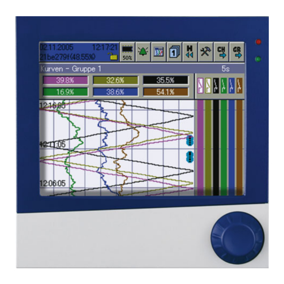
5 Functional test After the paperless recorder has been installed and wired up, it can be commissioned. After applying or switching on the supply voltage, the start-up screen will appear for a short time. Start-up screen The visualization will start automatically after the initialization phase. Visualization The paperless recorder is now in the recording phase. - Page 32 5 Functional test...
-
Page 33: Technical Data (Extract From Data Sheet)
6 Technical data (extract from data sheet) Analog inputs Thermocouple Designation Type Standard Meas. range Accuracy Fe-CuNi DIN 43 710 -200 to +900°C ±0.1% Fe-CuNi EN 60 584 -200 to +1200°C ±0.1% from -100°C Cu-CuNi DIN 43 710 -200 to +600°C ±0.1% from -150°C ±0.1% from -150°C Cu-CuNi... - Page 34 6 Technical data (extract from data sheet) Designation Standard Connection circuit Meas. range Accuracy Meas. curr. Cu 100 GOST 6651-94 A.4 2/3-wire -50 to +100°C ±0.5°C ≈ 250μA 2/3-wire -50 to +200°C ±0.9°C ≈ 250μA (TC = 4.26*10 1/°C) 4-wire -50 to +100°C ±0.5°C ≈...
- Page 35 6 Technical data (extract from data sheet) Transducer short circuit/break Short-circuit Break Thermocouple not detected detected Resistance thermometer detected detected Resistance transmitter not detected detected Potentiometer not detected detected Voltage ≤ ± 210mV not detected detected Voltage > ± 210mV not detected not detected Current...
- Page 36 6 Technical data (extract from data sheet) Screen Resolution / size 320 x 240 pixels / 5.5" Type / number of colors TFT color screen / 256 colors Screen refresh rate > 150Hz Brightness setting adjustable on instrument Screen saver (switch-off) through waiting time or control signal Electrical data Supply voltage (switch-mode PSU)
-
Page 37: Declaration Of Conformity
7 Declaration of Conformity... - Page 38 7 Declaration of Conformity...
-
Page 39: Type Examination Certificate
8 Type Examination Certificate... - Page 40 8 Type Examination Certificate...
- Page 41 8 Type Examination Certificate...
- Page 42 8 Type Examination Certificate...
- Page 43 9 Index Accessories Back panel Climatic conditions Commissioning CompactFlash Connection diagram Documentation, arrangement of Electrical connection Electrostatic discharge (ESD) Explosive atmosphere Functional test Installation Installation notes Installation site Instrument documentation in printed form Instrument documentation in the form of PDF files Instrument version, identification of Intended use Introduction...
- Page 44 9 Index Panel cut-out Panel mounting Returning RL 94/9/EG Safe use Standard accessories Start-up screen Technical data Type designation Typographical conventions Visualization level Warning signs Warranty...
- Page 48 JUMO GmbH & Co. KG JUMO Instrument Co. Ltd. JUMO Process Control, Inc. Street address: JUMO House 8 Technology Boulevard Moritz-Juchheim-Straße 1 Temple Bank, Riverway Canastota, NY 13032, USA 36039 Fulda, Germany Harlow, Essex CM20 2DY, UK Phone: 315-697-JUMO Delivery address:...
Need help?
Do you have a question about the LOGOSCREEN nt and is the answer not in the manual?
Questions and answers