Table of Contents
Advertisement
Quick Links
Advertisement
Table of Contents

Related Manuals for Carrier TeLINK


Summary of Contents for Carrier TeLINK
- Page 1 TeLINK Overview and Configuration Manual...
- Page 2 TeLINK Overview and Configuration Manual...
- Page 3 This document is the property of Carrier Corporation and is delivered on the express condition that it is not to be disclosed, reproduced in whole or in part, or used for manufacture by anyone other than Carrier Corporation without its written consent, and that no right is granted to disclose or so use any information contained in said document.
- Page 4 Manual Revisions The TeLINK Overview and Configuration Manual is catalog number 808-971, Rev. 11/99. It replaces the TeLINK Overview and Configuration Manual 808-971, Rev. 6/97. The revisions are listed below. Section/Chapter Changes Configuration Added a note regarding alarm acknowledgement operation to the Alarm Processing Definition Table's Alarm Acknowledger decision.
-
Page 6: Table Of Contents
Controller Identification (Ctlr-ID) Table ....20 Modem Configuration (MODEMCFG) Table ..20 Monitoring Center Definition (MONTRDEF) Table ..........21 TeLINK Configuration (RCSI_CFG) Table .... 23 Occupancy Configuration (OCCPC01S) Table ................. 25 Maintenance ..............27 Alarm Maintenance (ALARMMNT) Table ..... 27 Monitoring Center Maintenance (MONCTMNT) Table.......... - Page 7 Table Configuration for Transmitting Alarms ..........41 Appendix D ................ 43 Table Configuration for Receiving Alarms ............. 43 Appendix E ................. 44 TeLINK-Generated Alarms and Alerts ....44 Index ................... 45 Figures Figure 1 Example of TeLINK Linking Two CCNs ..........3 Figure 2 TeLINK ..........
- Page 8 Figure 9 Alarm Maintenance (ALARMMNT) Table ......27 Figure 10 Monitoring Center Maintenance (MONCTMNT) Table ......28 Figure 11 TeLINK Maintenance (RCSI_MNT) Table ............. 29 Figure 12 Alarm Handling at a Monitored Site ............39 Figure 13 ComfortWORKS or Building Supervisor-Initiated Calls...
- Page 9 viii...
-
Page 10: Introduction
Introduction... -
Page 11: About This Manual
Introduction This manual contains information about the functions of TeLINK About this Manual and how the user configures the TeLINK control module to perform those functions. The manual is divided into the following sections: • Introduction • Operating Characteristics •... -
Page 12: Telink
The TeLINK control module serves as an interface device between a TeLINK Carrier Comfort Network (CCN) and a modem. The module and modem enable the CCN to communicate over telephone lines with other similarly equipped CCNs. In this manual, the terms monitoring site and monitored site are used to refer to two CCNs linked together as illustrated in Figure 1. -
Page 13: Example Of Telink Linking Two Ccns
Figure 1 ComfortWORKS Example of TeLINK Linking (Optional) Two CCNs TeLINK Monitored Site Carrier System Comfort Elements Carrier Network (Optional) System Comfort (CCN) Elements Network (CCN) TeLINK Monitoring Site ComfortWORKS... -
Page 15: Operating Characteristics
Operating Characteristics... -
Page 16: Control Module
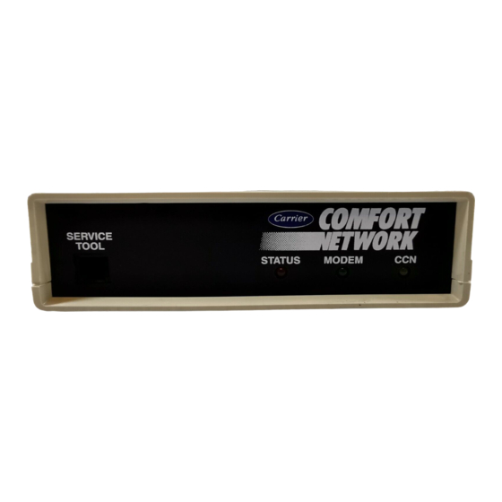
Operating Characteristics TeLINK is a device similar in appearance to an external modem. It can be placed on a desktop or inside a standard NEMA enclosure. It consists of an electronic control module with a PCMCIA-Type II modem card and power supply. The modem card and power supply can be purchased with the module or separately. - Page 17 Figure 2 TeLINK (front and back views) Front Back...
- Page 18 Yellow no activity on CCN blinking (rapidly) activity on CCN The TeLINK module features a Network Service Tool connector on Connectors the front, and CCN bus, power, and modem connectors on the back. They are described in the table below.
- Page 19 Signal ground Data (-) Modem for Use TeLINK is designed to use a factory- or user-supplied PCMCIA with TeLINK (Type II) modem, which supports the AT command set and response codes. The default configuration is for the U.S. Robotics® 28800 modem type.
-
Page 20: Telink Configuration Tables
The user configures TeLINK by means of the following tables: TeLINK Configuration Alarm Processing Definition Table Tables Controller Identification Table Modem Configuration Table Monitoring Center Definition Table TeLINK Configuration Table Occupancy Table The user configures these tables from a ComfortWORKS, the Building Supervisor, or a Network Service Tool. - Page 21 This table (MONTRDEF) contains decisions related to alarm report- Definition Table ing to a monitoring site or beeper service. A TeLINK contains two types of phone numbers. The Occupied phone numbers are those that are to be dialed to transmit alarms during occupied periods (typically during the daytime).
-
Page 22: Figure 3A
Figure 3a Occupied State - Occupied Alarms reported to a monitoring site Bldg 2 - monitored site Occupied Customer 127 ComfortWORKS Bldg 3 - monitored site Customer 127 Bldg 1 - monitoring site Customer 127 Occupied Bldg 4 - monitored site Customer 127 Figure 3b Unoccupied State -... -
Page 23: Telink Maintenance Tables
The state can be either occupied or unoccupied. When the current time in the TeLINK falls within any of the configured periods, the state of occupancy will be occupied, otherwise the state will be unoccupied. -
Page 24: Sequence Of Operation
Maintenance section. When an alarm or alert is generated by a system element at the Sequence of monitored site and the TeLINK buffer is not full, the monitored Operation site’s TeLINK will perform a sequence of operations. Refer to the Monitoring Center Definition (MONTRDEF) Table and... - Page 25 (occupied), and another number to be dialed during other times (unoccupied). TeLINK makes one attempt to dial the beeper service. If the con- nection is successful, TeLINK transmits its phone number to the beeper service, waits, and then hangs up.
- Page 26 If the buffer is not full, then no transmission occurs. How the Monitoring Site When the monitoring site’s TeLINK receives alarm(s)/alert(s) from Transmits Alarm(s)/ a monitored site, it sends a message to the monitored site acknowl- Alert(s) on Its Own edging the alarm or alert.
-
Page 28: Configuration
Configuration... -
Page 29: Alarm Processing Definition (Alarmdef) Table
Configuration TeLINK operation is controlled by decisions entered in a group of configuration tables. Each TeLINK contains the following configu- ration tables: ALARMDEF Alarm Processing Definition Table Ctlr-ID Controller Identification Table MODEMCFG Modem Configuration Table MONTRDEF Monitoring Center Definition Table... - Page 30 Yes/No Allowable Entries Default Value This decision is used to specify whether this TeLINK acts as the Alarm Acknowledger? alarm acknowledger for its CCN. There can be only one alarm acknowledger per CCN. Alarm acknowledging and alarm transmitting are two independent functions.
- Page 31 Building Number CCN system that contains this TeLINK. This number is included as part of the alarm message when the TeLINK transmits alarms to a monitoring site’s ComfortWORKS or Building Supervisor. The building number decision is used to identify the origin of an alarm for networks that have multiple buildings reporting alarms to a monitoring site.
-
Page 32: Controller Identification (Ctlr-Id) Table
(Ctlr-ID) Table this table, you can change the name, description, and location that appears for a TeLINK in the ComfortWORKS Controller List or the Building Supervisor’s Carrier Controls list, and in NDS Reports. Figure 5 illustrates a Modem Configuration Table. The table con- Modem sists of two decisions for configuring modem command strings. -
Page 33: Monitoring Center Definition (Montrdef) Table
Figure 6 below illustrates the Monitoring Center Definition Table. Monitoring Center An explanation of each configuration decision in the table follows. Definition (MONTRDEF) Table There are two types of phone number decisions. The Occupied Monitoring Center and Beeper decisions are used when dialing for alarm/alert transmission during occupied states. - Page 34 Default Value These decisions specify the time between establishment of a connec- Occ Beeper/Unocc tion to the beeper service and transmission of the TeLINK phone Beeper Delay Time number. This time is initiated after the dial command is issued, compensating for variations in connect times among beeper ser- vices.
-
Page 35: Telink Configuration (Rcsi_Cfg) Table
Default Value RCSI Password This decision is used to specify a password that must be transmitted to TeLINK in order to gain access to its CCN. If no password is entered in this decision, the default password, CARRIER, will be transmitted. - Page 36 Activate NDS This decision is used to enable or disable the operation of the NDS software. There should be only one active NDS on each CCN Communication Bus. In that NDS, this decision must be set to Yes. In any other NDS that may be present on the same bus, this decision must be set to No.
-
Page 37: Occupancy Configuration (Occpc01S) Table
Figure 8 below illustrates the Occupancy Configuration Table. An Occupancy explanation of the configuration decisions in the table follows. Configuration (OCCPC01S) Each time schedule consists of eight periods. You can configure each period’s time span and day(s) of the week when the occupancy Table state will be in effect. - Page 38 Period 1 - 8 Day Flags This decision is used to specify the day(s) that the period’s Occu- (MTWTFSSH) pied From and Occupied To values are in effect. From left to right, the first seven positions of the decision’s data entry field represent Monday through Sunday.
-
Page 39: Maintenance
Maintenance... -
Page 40: Alarm Maintenance (Alarmmnt) Table
TeLINK Maintenance Table Figure 9 illustrates the Alarm Maintenance Table. This table dis- Alarm plays the data for all of the alarms currently stored in the TeLINK. Maintenance The maintenance values displayed in this table are read-only up- dated values. An explanation of each value in the table follows. -
Page 41: Monitoring Center Maintenance (Monctmnt) Table
Alarm x Status This value displays REPORTED if the alarm was successfully transmitted through the network, or PENDING if the alarm has yet to be successfully sent. REPORTED/PENDING Valid Display Figure 10 illustrates the Monitoring Center Maintenance Table. Monitoring Center This table displays the status data for the occupied and unoccupied Maintenance centers. -
Page 42: Telink Maintenance (Rcsi_Mnt) Table
Valid Display Figure 11 illustrates a TeLINK Maintenance Table. This table TeLINK displays information regarding the status of the TeLINK. With the Maintenance exception of the first entry, the maintenance values displayed in this table are read-only displays of updated values. An explanation of (RCSI_MNT) Table each TeLINK maintenance value follows. - Page 43 Allowable Entries Unoccupied state: force this value to 2. Default Connection Status This field displays the current status of TeLINK phone network processing. One of the following messages will appear in this field: Message Current Status of Phone Network Idle No activity.
- Page 44 Valid Display This field indicates that the alarm buffer is currently full of alarms Alarm Buffer Full? or alerts (contains 4), and TeLINK is in the process of trying to report them. A full alarm buffer will also affect alarm Note: acknowledgement.
- Page 45 Yes/No Display Units Clock Initialized? This field indicates whether the timed broadcast has updated the TeLINK time and date. Yes/No Display Units Occupied Yes is displayed here if the time schedule is in an occupied mode (state). It displays No if the time schedule is in an unoccupied state.
-
Page 46: Configuration Sheets
Configuration Sheets... - Page 47 COMFORT NETWORK Controller Name:_______________________________ Bus #___________ Element #___________ Table Description:_____________________________________________________ Table Name: ALARMDEF ALARM PROCESSING DEFINITION TABLE CONFIGURATION SHEET Units Description Value Limits Alarm Services Holiday Alarm Reporting Yes/No Alarm When Occupied? Yes/No Alarm When Unoccupied? Yes/No Alarm Threshold Beeper When Occupied? Yes/No Beeper When Unoccupied? Yes/No...
- Page 48 COMFORT NETWORK Controller Name:_______________________________ Bus #___________ Element #___________ Table Description:_____________________________________________________ Table Name: MODEMCFG MODEM TABLE CONFIGURATION SHEET Units Description Value Limits Modem Services 24 characters Text Modem Config String 1 Modem Config String 2 Text 24 characters...
- Page 49 COMFORT NETWORK Controller Name:_______________________________ Bus #___________ Element #___________ Table Description:_____________________________________________________ Table Name: MONTRDEF MONITORING CENTER DEFINITION TABLE CONFIGURATION SHEET Units Description Limits Value Occ Monitoring Center Primary Phone Number 24 characters Text Text Secondary Phone Number 24 characters 8 characters Text Password Unocc Monitoring Center...
- Page 50 COMFORT NETWORK Controller Name:_______________________________ Bus #___________ Element #___________ Table Description:_____________________________________________________ Table Name: OCCPC01S OCCUPANCY CONFIGURATION TABLE CONFIGURATION SHEET Description Limits Units Value Timed Override Hours Period 1 DOW (MTWTFSSH) 11111111 Occupied from 00:00 Occupied to 24:00 Period 2 DOW (MTWTFSSH) 00000000 Occupied from 00:00...
- Page 51 COMFORT NETWORK Controller Name:_______________________________ Bus #___________ Element #___________ Table Description:_____________________________________________________ Table Name: RCSI_CFG TeLINK CONFIGURATION TABLE CONFIGURATION SHEET Units Description Value Limits Connect Services 16 characters RCSI Phone Number Text RCSI Password 8 characters Text Yes/No Activate NDS...
- Page 53 Appendixes...
-
Page 54: Handling Of Outgoing Alarms From Local Network
Appendix A The following flowchart depicts how a monitored site's TeLINK Handling of handles alarms. Outgoing Alarms from Local I d l e s t a t e Network A l m A c k & Figure 12 ( (Alm When Occ... -
Page 55: Comfortworks Or Building Supervisor-Initiated Calls
C o m f o r t W O R K S t r a n s m i t s Figure 13 t o TeLINK t h e t e l e p h o n e ComfortWORKS or... -
Page 56: Transmitting Alarms
Appendix C These tables indicate the values that must be configured to enable Table the monitored site's TeLINK to transmit alarms. Configuration for Transmitting Alarms Alarm Processing Table Decision Name Entry at Monitored Site's TeLINK Alarm When Specifies when TeLINK transmits... - Page 57 TeLINK Configuration Decision Name Entry at Monitored Site's TeLINK Table RCSI Phone Number Phone number of up to 16 characters RCSI Password Password of up to eight characters that matches the password configured in a TeLINK Configuration Table at the...
-
Page 58: Receiving Alarms
Appendix D These tables indicate the values that must be configured for a moni- Table toring site's TeLINK to enable it to receive alarms. Configuration for Receiving Alarms Alarm Processing Table Decision Name Entry at Monitoring Site's TeLINK Building Number Identification number (0-255) assigned to the TeLINK’s CCN... -
Page 59: Telink-Generated Alarms And Alerts
Appendix E This table explains the TeLINK-generated alarm and alert messages. TeLINK-Generated Alarms and Alerts Alarm/Alert Message Displayed Reason for Message Inactivity Timeout Thirty minutes of inactivity has elapsed. The monitored site's TeLINK sends this alert message to its CCN to indicate that it has disconnected from the monitoring site. - Page 60 Index...
-
Page 61: Index
2 MODEMCFG Configuration sequence of operations 13 Table 10, 20 status messages 30 Modems stored in TeLINK 12, 27 default configuration 8 successful transmission 28 MONCTMNT Maintenance threshold 13 Table 12, 28 to beeper service 14... - Page 62 23 Phone Numbers 22, 23 RCSI_CFG Configuration Table 10, 23 RCSI_MNT Maintenance Table 12, 29 Self-Health Check 9 schedule 19 TeLINK alarm handling 39 default address 5 functions 2 password 23 phone number 23 user interfaces for 9 Time Schedules 12...
- Page 63 Reader's Your comments regarding this manual will help us improve future editions. Please comment on the usefulness and readability of this Comments manual, suggest additions and deletions, and list specific errors and omissions. Document Name: Publication Date: Usefulness and Readability: Suggested Additions and Deletions: Errors and Omissions (Please give page numbers): Date:...
- Page 64 Carrier Corporation Carrier World Headquarters Building One Carrier Place Farmington, CT 06034-4015 Attn: CCN Documentation...
- Page 65 Printed in U.S.A. 808 - 971 Rev. 11/99...
Need help?
Do you have a question about the TeLINK and is the answer not in the manual?
Questions and answers