AGS PARKSAFE Installation Operation & Maintenance
Ventilation control panel
Hide thumbs
Also See for PARKSAFE:
- Installation & operation manual (16 pages) ,
- Installation & operation manual (16 pages) ,
- Installation, operation & maintenance manual (20 pages)
Table of Contents
Advertisement
Quick Links
Installation, Operation & Maintenance
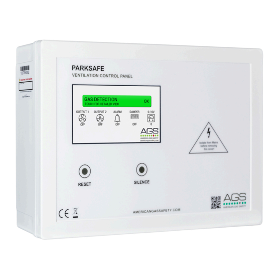
Parksafe Ventilation Control Panel
The control panel designed to be paired with Parksafe Nitrogen Dioxide (NO
for installation in car parking facilities and enclosed garages. The control panel will monitor up to 16 gas detectors per
cable run and automatically control ventilation systems according to gas levels and temperature.
The information contained within this manual should be referenced for typical installation and operation only.
For specific requirements that may deviate from the information in this manual – contact your supplier.
Rev: 13
0721
Ventilation Control System
Installation, Operation & Maintenance
Please read this manual carefully and retain for future use.
Parksafe Control Panel
) and Carbon Monoxide (CO) gas detectors
2
1
Advertisement
Table of Contents

Subscribe to Our Youtube Channel
Related Manuals for AGS PARKSAFE


Summary of Contents for AGS PARKSAFE
- Page 1 Installation, Operation & Maintenance Please read this manual carefully and retain for future use. The control panel designed to be paired with Parksafe Nitrogen Dioxide (NO ) and Carbon Monoxide (CO) gas detectors for installation in car parking facilities and enclosed garages. The control panel will monitor up to 16 gas detectors per cable run and automatically control ventilation systems according to gas levels and temperature.
-
Page 2: Table Of Contents
Installation, Operation & Maintenance Parksafe Control Panel Content Important Warning Statements ..............3 Installation ....................4 Typical Location and Positioning ..................4 Access & Mounting ........................ 5 Main Board Overview ......................5 Main Board Connections ...................... 6 Wiring a Detector ........................7 Wiring a Detector Chain ...................... -
Page 3: Important Warning Statements
The expected lifetime of a CO gas sensor element is 5 years upon initial power up. The Parksafe control panel will display a message to indicate this time and detectors should immediately be replaced. -
Page 4: Installation
The Parksafe will make or break a dry contact internally on terminals: OUTPUT 1 and a second contact on OUTPUT 2. This is to have a live feed to the ventilation system wired through the contact so that the Parksafe can activate ventilation/ fans, this can either be via a direct live feed or via a run signal. -
Page 5: Access & Mounting
Installation, Operation & Maintenance Parksafe Control Panel Access & Mounting Unpack all the parts! Designed for surface mounting, it must be installed by a licensed, insured contractor. Carefully remove the front cover from the unit by unscrewing the four bolts located at each corner. To do this – use the socket wrench provided. -
Page 6: Main Board Connections
DETECTOR CHAIN. 24vdc power and Modbus data is wired to Parksafe gas detectors [DETECTOR CHAIN] - [+ / - / D+ / D-]. Up to 16 detectors can be connected, chained in parallel up to approx. 500 yards from the panel depending on chain configuration, wire type for power and condition. -
Page 7: Wiring A Detector
Wiring a Detector Chain Up to 16 Parksafe detectors can be connected, chained in a parallel ‘daisy chain’ method up to approx. 500 yards from the panel depending on chain configuration, wire type for power and condition. Any other way may cause issues or damage to the overall system. -
Page 8: Detector Id Switches
On the front display circuit board you’ll find a SETTINGS switch – when switched on, the screen will display the settings menu – you can now configure your Parksafe system. When changes have been made – turn the settings switch off and the panel will restart! -
Page 9: Settings Menu
Installation, Operation & Maintenance Parksafe Control Panel Settings Menu The Parksafe panel has a touch screen which allows the engineer/user to configure the system. Adjust the screen brightness. Change/select option (Press or slide the cursor up and down) (Press the blue option box or press and hold) -
Page 10: Installation Tips
Installation, Operation & Maintenance Parksafe Control Panel Installation Tips CONNECTION The best way to connect devices in a MODBUS RTU is a ‘DAISY CHAIN’ method. MAXIMUM DISTANCE You may encounter problems when powering gas sensors beyond 500 yards from one control panel, in this instance, contact your supplier. -
Page 11: Operation
Operation First Power Up Upon connecting mains power, the Parksafe control panel will load for approximately 60 seconds. During this time the screen will display an ‘initialising’ screen. The panel will then begin establishing signals with any Parksafe gas detectors. -
Page 12: Silence & Reset
Installation, Operation & Maintenance Parksafe Control Panel Silence & Reset To silence the internal buzzer – press the Silence button on the front panel. This will also silence any external audio sounders connected to the panel. If the system reaches alarm condition – the panel will need to be reset when the gas levels detected return to a safe level. -
Page 13: General Maintenance
It is recommended that the system be serviced at least annually from the date of installation for optimum performance and protection due to sensitivity drifts. A service message will appear on the Parksafe control panel after one year of detector operation. The detector will still operate during this time but contact your supplier immediately. -
Page 14: Bump Test (Gas Response Check)
IF YOU ARE TESTING THE ACTUATION OF OUTPUTS / RELAYS, PROCEED TO STEP 2. STEP 1. • Access service mode by pressing the AGS logo on the control panel main screen only. The screen will display a service prompt. Press Yes. (Note: All alarm signals/outputs will be inhibited for fifteen (15) minutes. •... -
Page 15: Specification
Max. Power Consumption 14.5W Power Voltage Input Range 100-240vac Outputs Ventilation System Outputs x2 / Alarm / Damper / Parksafe Detector / Sounder/Strobe / 24vdc / 0-10vdc Communication RS485 MODBUS RTU Relay(s) 4x 120vac 6A Max (Non Latching Switch) 1x24vdc Terminal Wire ratings Copper 18AWG (0.75mm2) Min. - Page 16 Every effort is made to ensure the accuracy of this document; however, AGS can assume no responsibility for any errors or omissions in this document or their consequences. AGS would greatly appreciate being informed of any errors or omissions that may be found in the content of this document.
Need help?
Do you have a question about the PARKSAFE and is the answer not in the manual?
Questions and answers