Table of Contents
Advertisement
Quick Links
Advertisement
Table of Contents

Subscribe to Our Youtube Channel
Related Manuals for Force 10 S2410


Summary of Contents for Force 10 S2410
- Page 1 Installing the S2410 System August 2007...
- Page 2 In the interest of improving internal design, operational function, and/or reliability, Force10 Networks reserves the right to make changes to products described in this document without notice. Force10 Networks does not assume any liability that may occur due to the use or application of the product(s) described herein.
-
Page 3: Table Of Contents
Installing the S2410 ........ - Page 4 S2410 Specifications ........
-
Page 5: Preface
S2410 system, including the S2410CP and S2410P. After you have completed the hardware installation and power-up of the S2410, refer to the SFTOS™ Configuration Guide for the S2410 for software configuration information and the SFTOS Command Reference, Version 2.4 for detailed Command Line Interface (CLI) information. -
Page 6: Related Publications
• S2410 Quick Reference • S-Series and SFTOS Version 2.4.1 Release Notes Each of these documents are available on the S2410 Documentation CD-ROM and on the iSupport website (registration for access to some sections is required): https://www.force10networks.com/csportal20/ KnowledgeBase/Documentation.aspx The iSupport website also has a section for S-Series techtips and FAQs. See... -
Page 7: The S2410 System
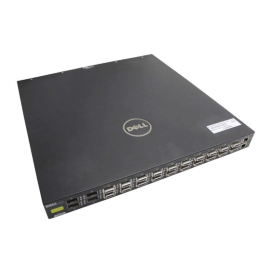
System Status on page 9 Physical Interfaces The Force10 Networks S2410 is a Layer 2 switch that is available in two models — the S2410CP and the S2410P. The primary difference is that the S2410P contains 24 built-in 10-gigabit Ethernet (10G) XFP ports, while the S2410CP contains 20 built-in 10G BaseCX4 ports and four 10G XFP ports. -
Page 8: Required Equipment
The following items are necessary to install the S2410 system: • Two grounded AC power sources • At least one cable (included) to connect the power source to the S2410 AC power supply • Brackets and screws (included) for front-mounted rack installation (#2 Phillips screwdriver required but not included) •... -
Page 9: System Status
System Status S2410 status data can be derived in several ways, including physical LED displays, discussed next, along show with boot menu options, CLI commands, SNMP traps, and the SFTOS Web User Interface. For details on those options, see the S2410 Quick Reference, the SFTOS Command Reference (SFTOS 2.4), and the SFTOS Configuration Guide (SFTOS 2.4). - Page 10 10/100 Ethernet (labeled Off — No Link detected at this port (commonly called the service port) Activity LED (lower right side of port) Blinking Green — Activity, transmitting or receiving packet at this port. Off — No activity The S2410 System...
-
Page 11: Site Preparation
Note: Install the S2410 into a rack or cabinet before installing any optional components. Site Selection Make sure that the area where you install your S2410 chassis meets the following safety requirements: • Near an adequate power source. Connect the system to the appropriate branch circuit protection as defined by your local electrical codes. -
Page 12: Cabinet Placement
As listed in Table 2, “Status Panel LED Display,” on page 9, the front panel of the S2410 has an Alarm LED that includes alarms for fan problems and out-of-range temperatures. The LED is amber when the temperature or components are outside expected parameters, red in a major alarm. -
Page 13: Power
Both S2410 models (S2410CP and S2410P) provide built-in dual AC power supplies. Ideally, the power sources would be on separate circuits. While only one power supply is needed for the unit to operate, if both power supplies are connected, the power supplies act as redundant backups and do some load sharing, although the sharing is not necessarily equal. - Page 14 Site Preparation...
-
Page 15: Installing The S2410
Installing the S2410 S2410 systems have no stacking or other optional modules, so, to install the S2410 system, you can simply install the system on a tabletop, in a rack, or in a cabinet, turn it on, and then connect ports. The following options are discussed in this chapter: •... -
Page 16: Attaching The Rack Ears
Figure 3 shows the positioning of the rack ears and screws. Note that the rack ears supplied with the S2410 have a hole in the middle to accommodate the vent in the S2410. Figure 3 Attaching Rack Ears to Switch... -
Page 17: Two-Post Rack Mounting
Site Preparation, on page 11). If you are installing two S2410 systems side-by-side, position the two S2410 chassis at least 5 inches (12.7 cm) apart to permit proper airflow. Position the S2410 chassis in the rack (attach the rack ears first, using only the supplied screws; see Attaching the Rack Ears on page 16). -
Page 18: Four-Post Rack-Mounting With Threaded Rails
Attach the rack ears first, using only the supplied screws (see Attaching the Rack Ears on page 16), and then follow the steps below to install the S2410 chassis into a four-post 19-inch equipment rack, using the attached front mounting brackets and the optional adjustable rear-mounting brackets. Step... - Page 19 Step Task Insert the S2410 into the rack, and secure the chassis to the front post with two screws. Then secure the chassis to the rear posts with two screws. Set the adjustable rear mounting bracket to the length (one of three lengths) for your bracket. Secure the length with the four screws.
-
Page 20: Four-Post Rack-Mounting With Cage Nuts
Attach the rack ears first, using only the supplied screws (see Attaching the Rack Ears on page 16), and then follow the steps below to install the S2410 chassis into a four-post rack mounting with cage nuts. Step Task Attach the two rear brackets to the side panels. Align the three holes in the bracket with the three holes on the S2410 chassis, and secure the brackets to the chassis using the screws. - Page 21 Position the cage nuts over the holes on each bracket flange and each rack post. Align the rack filler panel to the rear bracket and rack posts. Secure by inserting two screws into the hole in the filler panel through to the holes in the rack post. Installing the S2410 System...
-
Page 22: Supplying Power
The power cords shipped by default with the S2410 chassis are for the United States. Several versions of the power cord are available, based on country requirements. Connect the power cord plugs to the AC receptacles at each rear corner of the S2410, as shown in Figure 2 on page 7, making sure the cords are secure. -
Page 23: Accessing Ports
Ethernet Management port (see Accessing the Ethernet Management Port on page 24). For more on using alternative management interfaces, see the S2410 Quick Reference or the Getting Started chapter of the SFTOS Configuration Guide for the S2410. Connect the RJ-45/DB-9... -
Page 24: Accessing The Ethernet Management Port
Using any cable that is not approved by Force10 might cause interface errors and/or have issues with mechanical fit. CX4 cables are not included with the S2410, but Force10 has certified cables to use with the S2410. For a list of approved cables, see the S2410 data sheet: http://www.force10networks.com/products/s2410.asp... -
Page 25: Required Cx4 Cable Housing Clearances
Required CX4 Cable Housing Clearances on page Note: The S2410 CX4 ports auto-sense the length of the attached cable, so their pre-emphasis does not need to be set manually. Required CX4 Cable Housing Clearances... -
Page 26: Accessing Xfp Ports
All ports except the dedicated Ethernet Management port in the S2410P use XFP transceivers, and the S2410CP includes four XFP ports. Each XFP port requires an XFP transceiver (not included in the S2410 chassis shipping box), which is a small rectangular module (see... -
Page 27: S2410 Specifications
-4° to 158°F (-20° to 70°C) non-operating Maximum Acceptable No performance degradation to 10,000 feet (3,048 meters) Altitude Relative Humidity Operating: 10 to 90% relative humidity (RH) non-condensing Storage: 10 to 95% RH non-condensing Shock MIL-STD-810 Vibration Bellcore GR-63 Installing the S2410 System... -
Page 28: Ac Power Supply
Load balancing and redundant AC power Both the S2410CP model and the S2410P have two AC inputs that connect to separate sets of power modules for 1+1 redundancy. IEEE Standards The S2410 complies with the following IEEE standards: • 802.1ac Frame Extension for VLAN tagging •... -
Page 29: Agency Compliance
• 2570 SNMP v3 • 2665 Ethernet-like interfaces Agency Compliance The S2410 is designed to comply with the following safety and agency requirements. Safety Standards and Compliance Agency Certifications • CB Report, all country deviations • CE Mark (EN 60950) •... -
Page 30: Electromagnetic Emissions
• EN 61000-4-3 Radiated Immunity • EN 61000-4-4 EFT • EN 61000-4-5 Surge • EN 61000-4-6 Low Frequency Conducted Immunity • EN 300 386 v1.3.1 (2001-09) EMC for Network Equipment • EN 55024 1998 Telecoms: JATE (for Japan) S2410 Specifications... -
Page 31: Appendix A Technical Support
Appendix A Technical Support This appendix contains these major sections: • The iSupport Website • Contacting the Technical Assistance Center on page 32 • Locating Serial Numbers on page 33 • Requesting a Hardware Replacement on page 34 The iSupport Website The i-Support website (http://www.force10networks.com/support/), as shown below, provides a range of documents and tools to assist you with effectively using Force10 equipment and mitigating the impact of network outages. -
Page 32: Accessing Isupport Services
To access some iSupport services you must have a userid and password. If you do not have one, you can request one at the website: 1. On the Force10 Networks iSupport page, click the Account Request link. 2. Fill out the User Account Request form, and click Send. You will receive your userid and password by E-Mail. -
Page 33: Locating Serial Numbers
11 digits. You can also use the command in the CLI to access the serial number. 10/100 Ethernet Management Port Catalog # S2410-01-10GE-24P 10/100 Ethernet Status LEDs 4 XFP Ports... -
Page 34: Requesting A Hardware Replacement
Requesting a Hardware Replacement To request replacement hardware, follow these steps: Step Task Determine the part number and serial number of the component. To list the numbers for all components installed in the chassis, use the show inventory command. Request a Return Materials Authorization (RMA) number from TAC by opening a support case. Open a support case by: •... -
Page 35: Index
IEEE Standards contacting TAC (technical support) Immunity CX4 connector Installation CX4 Ports, Using Cabinet CX4 pre-emphasis Rack Tabletop installation brackets and screws Installing Ports DB-9 to RJ-45 iSupport depth of chassis Installing the S2410 System... - Page 36 S2410 front view S2410 rear view S2410 status information S2410 Web User Interface LED Displays Safety Standards LED, alarm screws for rack installation lineconfig command serial baudrate command Locating Serial Numbers serial number, switch Serial Numbers, Locating SFTOS Web User Interface...
- Page 37 Web User Interface, SFTOS width of chassis ventilation voltage XFP Installation XFP Ports, Using Web UI Installing the S2410 System...
Need help?
Do you have a question about the S2410 and is the answer not in the manual?
Questions and answers