Table of Contents
Advertisement
Quick Links
Advertisement
Table of Contents

Related Manuals for Force 10 S50


Summary of Contents for Force 10 S50
- Page 1 July 2006 100-00030-04...
- Page 2 In the interest of improving internal design, operational function, and/or reliability, Force10 Networks reserves the right to make changes to products described in this document without notice. Force10 Networks does not assume any liability that may occur due to the use or application of the product(s) described herein.
-
Page 3: Table Of Contents
Installing the S50 ........ - Page 4 Connecting Three S50 Switches ........
-
Page 5: Preface
This guide provides site preparation recommendations, step-by-step procedures for rack mounting and desk mounting, inserting optional modules, and connecting to a power source. After you have completed the hardware installation and power-up of the S50, refer to the SFTOS™ Configuration Guide for software configuration information and the SFTOS™ Command Reference for detailed Command Line Interface (CLI) information. -
Page 6: Related Publications
Related Publications For more information about the S50, refer to the following documents: • SFTOS™ Configuration Guide • SFTOS Command Reference • S50 Quick Reference • S-Series and SFTOS Release Notes Each of these documents are available on the product CD-ROM and on the iSupport website (registration for access to some sections is required): https://www.force10networks.com/csportal20/KnowledgeBase/Documentation.aspx... -
Page 7: The S50 System
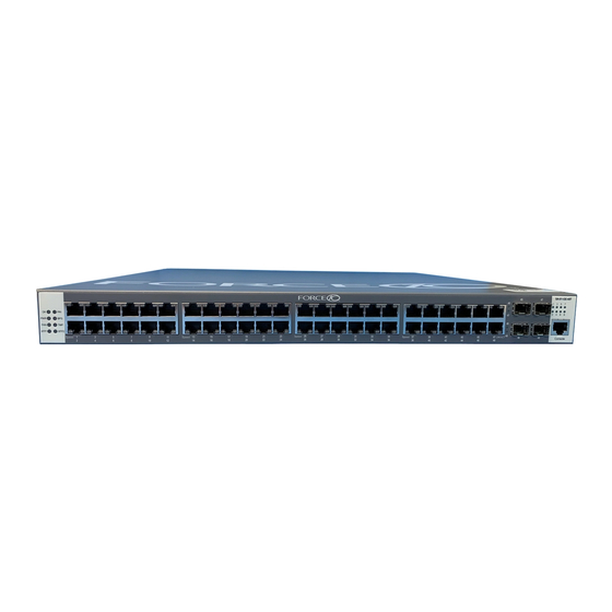
Chapter 1 The S50 System The Force10 Networks S50 is a high performance, low cost, stackable, Layer 2 switch/Layer 3 router that supports 48 built-in 10/100/1000 Base-T ports, four SFP (small form-factor pluggable) ports, and two optional 10-Gigabit XFP or CX4 ports. For stacking details, see... -
Page 8: Equipment
The switch • One grounded AC power source per S50 • Cable to connect the AC power source to the S50 chassis (included) • Brackets for rack installation (supplied) • Screws for rack installation and #2 Phillips screwdriver (not supplied) Other optional components are: •... -
Page 9: System Status
System Status S50 status information can be derived in several ways, including physical LED displays and boot menu options, both discussed here, along with CLI “show” commands, SNMP traps, and the SFTOS Web User Interface. For details on those options, see the SFTOS Command Reference and the SFTOS Configuration Guide. - Page 10 Green Redundant power supply is operating outside expected parameters or Amber is not installed. Green Temperature is OK. TEMP Amber Temperature is operating outside expected parameters. Green 10G2 link XFP2 Blinking Green 10G2 active 10G2 no link The S50 System...
-
Page 11: Site Preparations
Note: Install the S50 into a rack or cabinet before installing any optional components. Site Selection Make sure that the area where you install your S50 chassis meets the following safety requirements: • Near an adequate power source. Connect the system to the appropriate branch circuit protection as defined by your local electrical codes. -
Page 12: Cabinet Placement
(12.7 cm) of clearance around the side intake and exhaust vents. When two S50 systems are installed side by side, position the two S50 chassis at least 5 inches (12.7 cm) apart to permit proper airflow. The acceptable ambient temperature ranges are listed in... -
Page 13: Power
Power Use the power cord shipped with the S50 chassis to connect the chassis to the AC power outlet. Caution: The power supply cord is used as the main disconnect device; ensure that the socket-outlet is located/installed near the equipment and is easily accessible. - Page 14 Site Preparations...
-
Page 15: Installing The S50
Always wear an ESD-preventive wrist or heel ground strap when handling the S50 and its components. Inserting the 10-Gigabit Module (optional) The S50 has a slot at the right rear of the chassis, for which there are two types of 10-Gigabit module available (see Figure 2)—fiber (optical) and copper (10GBase-CX4). -
Page 16: Inserting Backup Power (Optional)
The S50 can be positioned on a stable tabletop. Keep the following in mind when using a tabletop for your S50: • Ensure that your tabletop is stable and can handle the weight of the S50 or a stack of S50s, along with any added backup power supplies. •... -
Page 17: Two-Post Rack Mounting
If you are installing two S50 systems side-by-side, position the two S50 chassis at least 5 inches (12.7 cm) apart to permit proper airflow. Position the S50 chassis in the rack. Secure the chassis with two screws through each bracket and onto the rack post. -
Page 18: Four-Post Rack-Mounting With Threaded Rails
Align the three screw holes of the adjustable rear mounting bracket with the three holes in the S50 chassis, and secure the mounting bracket with three screws. Insert the S50 into the rack, and secure the chassis to the front post with two screws. Then secure the chassis to the rear posts with two screws. - Page 19 Step Task Set the adjustable rear mounting bracket to the length (one of three lengths) for your bracket. Secure the length with the four screws. Figure 4 Four-post Rack-mounting with Adjustable Rear-mounting Brackets Installing the S50 System...
-
Page 20: Four-Post Rack-Mounting With Cage Nuts
Align brackets Align and secure the adjustable bracket onto the rear bracket. Insert the S50 chassis into the rear of the rack. Position and secure the chassis with two screws into each front bracket flange and into the rack post. - Page 21 Position the cage nuts over the holes on each bracket flange and each rack post. Align the rack filler panel to the rear bracket and rack posts. Secure by inserting two screws into the hole in the filler panel through to the holes in the rack post. Installing the S50 System...
-
Page 22: Connecting Stacking Ports (Optional)
The number of S50s in a stack is limited by the number of S50s with 10Gb modules: — If zero or one S50 has a 10Gb module, the stack is limited to seven S50s. — If three S50s have a 10Gb module, the stack is limited to six S50s. -
Page 23: Connecting Three S50 Switches
Use the remaining cable to connect the top and bottom S50s by inserting one end of the cable into the open Stack Port B of the bottom S50 and the other end of the cable into Stack Port A of the top S50. -
Page 24: Supplying Power
Supplying Power Supply power to each S50 in the stack after they are mounted and the stack is connected. Use the supplied AC power cord to connect the S50 to the power source (see AC Power Requirements on page 36). If you... - Page 25 For details on using stack management commands, such as to remove a unit from a stack, see Chapter 6, Stacking Switches, in the SFTOS Configuration Guide, or see the Stacking Commands chapter in the SFTOS Command Reference. Installing the S50 System...
- Page 26 Installing the S50...
-
Page 27: Installing Backup Power
AC circuit, providing backup power to the S50 on a 1:1 basis. The DPM powers the S50 if there is no AC input. The AC input is preferred over the DPM, and does not share the load between the two power sources. -
Page 28: Installing The Backup Power Shelf (Optional)
Figure 9 S50 with Power Shelf Inserting the AC-to-DC Converter into the Shelf The power shelf can house up to eight AC-to- DC converters, one for each possible S50 in a stack. To install a converter into the power shelf, follow these steps:... -
Page 29: Installing The Dc Power Module
Installing the DC Power Module The DC power module is installed in the rear of the S50 chassis (see the figure in Step 3). To install this component, follow the steps below: Step Task Power down the S50. Remove the screws that secure the DC power module cover panel and then remove the cover panel. - Page 30 Step Task Insert the DC-to-DC cable from the converter to the DC power module in the S50, as shown below: DC Power Module DC-to-DC Cable AC-to-DC Converter Figure 11 AC-DC Converter Connected to DC Power Module Tighten the captive screws on the sides of the connector cable by turning them clockwise.
-
Page 31: Installing Ports
Figure 13 Front View of S50 Showing Console Port If necessary, connect the RJ-45/DB-9 adapter that is shipped with the S50 system to the end of the RJ-45 cable that will connect to your terminal. -
Page 32: Installing Sfps
To install SFPs into an open optical port at the right front of the switch, follow the steps below: Warning: Electrostatic discharge (ESD) damage can occur if components are mishandled. Always wear an ESD-preventive wrist or heel ground strap when handling the S50 and its components. -
Page 33: Installing Xfps
Warning: Electrostatic discharge (ESD) damage can occur if components are mishandled. Always wear an ESD-preventive wrist or heel ground strap when handling the S50 and its components. Warning: Do not look directly into any optical port. Failure to follow this warning could result in physical harm. - Page 34 Installing Ports...
-
Page 35: S50 Specifications
32° to 104°F (0° to 40°C) Temperature • -4° to 158°F (-20° to 70°C) non-operating Maximum altitude No performance degradation to 10,000 feet (3,048 meters) Relative humidity 10 to 95% non-condensing Shock MIL-STD-810 Vibration Bellcore GR-63 Installing the S50 System... -
Page 36: Ac Power Requirements
100 - 240 VAC, 50/60 Hz Maximum AC Power Supply Input Current 10 A @ 100 VAC per AC Power Supply Maximum System Power Input 3000W IEEE Standards The S50 complies with the following IEEE standards: • 802.3ae 10 Gigabit Ethernet • 802.3ab 1000Base-T •... -
Page 37: Agency Compliance
Agency Compliance The S50 is designed to comply with the following safety and agency requirements. Safety Standards and Compliance Agency Certifications • CUL 60950, 3rd edition • CSA 22.2 No. 60950 • EN 60950, Safety of Information Technology Equipment •... - Page 38 S50 Specifications...
-
Page 39: Index
S50 height width commands ground connector member grounding movemanagement no member show switch switch priority Hot-swapping Units in a Stack switch renumber Humidity Connecting Stacking Ports humidity, acceptable console port pinout Installing the S50 System... - Page 40 LEDs, port status RJ-45 installation LEDs, stacking LEDs, Status indicator limitations on numbers of units in a stack S2410 Web User Interface S50 front view S50 rear view MAC address S50 status information Maximum altitude Safety Standards member command...
- Page 41 System Status ventilation voltage Tabletop Installation temperature Web User Interface, SFTOS acceptable ambient range width of chassis fans and ventilation relative humidity XFP Installation storage XFP LINK/ACT temperature LED XFP Port LED terminal server terminal settings, console Installing the S50 System...
Need help?
Do you have a question about the S50 and is the answer not in the manual?
Questions and answers