Table of Contents
Advertisement
Quick Links
Advertisement
Table of Contents

Subscribe to Our Youtube Channel
Related Manuals for TSC CPX4P


Summary of Contents for TSC CPX4P
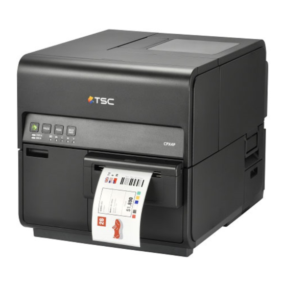
- Page 1 CPX4P COLOR INKJET LABEL PRINTER Service Manual...
- Page 2 Application The following paragraph does not apply to any countries where such provisions are This manual has been issued for qualified persons to learn technical theory, installation, inconsistent with local law. maintenance, and repair of products. This manual covers all localities where the products are sold.
- Page 3 Explanation of Symbols The following symbols are used throughout this Service Manual. The following rules apply throughout this Service Manual: Symbols Explanation Symbols Explanation 1. Each chapter contains sections explaining the purpose of specific functions and the relationship between electrical and mechanical systems with reference to the timing of Check.
-
Page 4: Table Of Contents
Internal View (Front) ....................9 Table of Contents Internal View (Rear) ....................9 Front Cross-sectional View ..................10 Horizontal Cross-sectional View ................10 Safety Precautions .................... 4 Operation Panel ..................... 11 Notes When Handling the Lithium Battery ..........4 2. Technology ....................12 Notes before Servicing ................ - Page 5 List of Parts ....................57 Removing Transport Unit ..................99 List of External Covers ................... 57 PCB ......................102 List of Main Units / Parts ..................58 Removing Needle Unit (Ink Tank Relay PCB) ............102 Periodic Replacing Parts, Durable Parts ..............59 Removing Operation Panel PCB ................
- Page 6 Cleaning Procedure of Printhead Face ..............126 Checking the Installation Environment ............... 196 Cleaning Procedure of TOF Sensor ..............128 Checking the Installation Space ................197 5. Troubleshooting ..................129 Installation Precautions ................. 197 Checking the Contents ................198 Initial Check ................... 129 Unpacking Procedure ................
-
Page 8: Safety Precautions
Safety Precautions Notes When Handling the Lithium Battery Notes before Servicing For CA, USA Only Included battery contains Perchlorate Material ---- special handling may apply. • At servicing, be sure to turn OFF the power source according to the specified steps and http://www.dtsc.ca.gov/hazardouswaste/perchlorate/ disconnect the power plug. -
Page 9: Product Overview
1. Product Overview Features Pigment Ink Pigment Ink is superior in weather resistance and water resistance, so it's possible to print on logistic label and display advertising which is required to keep color stability for a long time. High Speed and Fine Quality Printing Fine-quality printing at maximum printing speed of 150 mm/sec, at 1200 dpi for vertical scanning by 1200 dpi for horizontal scanning. -
Page 10: Specifications List
15 to 30 degrees Celsius (59 to 86 degrees Fahrenheit) , 10 to 80 % RH Specifications List Acoustic noise Sound pressure level (Fast mode)/Bystander position 40 dB or less (On standby) Specifications 60 dB or less (printing) Sound power Item Specifications level:... -
Page 11: Printhead
Printhead Cleaning Item Specifications Item Specifications Printheads 4.32 inch Monolithic Printhead Cleaning types Maintenance jet cleaning, wipe cleaning, and tube pump type suction 4 Printheads for Bk/C/M/Y cleaning Cleaning mode Automatic cleaning Print resolution 1200dpi At power ON, when Printer backs from sleep mode, before Amount of discharge 8+0-2ng printing, during printing, after printing etc. -
Page 12: Component Names
Component Names Rear View Front View Rear Feeder Slot USB Connector Power Socket LAN Connector RS-232C Connector Left Cover RS-232C Connector Upper Cover Right Cover Operation Panel Roll Cover Ink Tank Door Rear Cover Cutter Cover Maintenance Cartridge Door Maintenance Cover... -
Page 13: Internal View (Front)
Internal View (Rear) Internal View (Front) Pinch Roller Release Lever Paper Guide Maintenance Cartridge Upper Unit Open Lever Transport Guide Ink Tank Lever Transport Unit Roll Holder... -
Page 14: Front Cross-Sectional View
Horizontal Cross-sectional View Front Cross-sectional View Transport Sensor DC Power Supply PCB Unit Print Module Yellow Ink Tank Printhead Paper Suction Fan Pump Unit Magenta Ink Tan Upper TOF Sensor PCB Lower TOF Sensor PCB Printhead Lifter Part Cyan Ink Tan Roll Holder [10] Transport Belt... -
Page 15: Operation Panel
Operation Panel Power Key [PAUSE] Key [FEED] Key [BACK FEED] Key Ink Warning Lamp Maintenance Cartridge Lamp [ERROR] Lamp [STATUS] Lamp... -
Page 16: Technology
2. Technology Basic Configuration Ink Supply System Ink Supply System supplies ink from Ink Tank to Printheads, suctions ink from Printheads, and collects Functional Configuration waste ink from Purge Unit to Maintenance Cartridge. It consists of Ink Tank Holder Unit, Valve Unit, and This Printer mainly consists of 3 systems: Image Formation System, Ink Supply System, and Pump Unit in Print Module. - Page 17 Feeder/Transport System Feeder/Transport System feeds paper. It consists of Roll Drive Unit, Paper Guide Unit and Transport Unit. Roll Drive Unit Transport Unit Paper Guide Unit...
-
Page 18: Outline Of Electrical Circuits
Outline of Electrical Circuits Block diagrams of main circuits of Printer are shown below. Main electric circuits of this Printer include Printer Controller PCB and DC Power Supply PCB. Main control of this Printer is performed by the microcomputer installed on Printer Controller PCB. Printer Controller PCB performs image processing for the print data spooled from the host computer, and controls Printheads to print an image on a paper according to the processed print data. -
Page 19: Drive Configuration
Drive Configuration Roll Motor M101: M103: Purge Motor CL101: Valve Clutch Transport Motor M102: M104: Printhead Lift Motor CL102: Pump Clutch Valve Motor M106: M105: Pump Motor SL101: Buffer Solenoid... -
Page 20: Basic Sequence
Basic Sequence Outline Initialization processing that must be performed at power-on to allow Printer to perform printing properly is broadly classified into hardware start and initialization sequences. On the other hand, shutdown processing is performed at power-off to retain Printer condition normally until Printer is used next time. - Page 21 Initialization Sequence This is electrical initialization performed when Printer is turned on. Initialization is performed after completion of the hardware start process following power-on of Printer. In Update mode, no operation is performed. In Service mode, only cleaning for initialization is not Operations Details performed.
- Page 22 Shutdown Sequence The shutdown sequence is performed when Printer is turned off, Printer enters the sleep mode after lapse of a set time, or Service Call Error occurs. Operations Details When Service Call Error that disables mechanical operation has occurred, "cleaning" and "mechanical Print data clearing Clears the data stored in the memory.
-
Page 23: Power Supply
Power Supply Overview DC Power Supply Unit of Printer has 2 type of outputs, DC 5V and DC 24V. Each PCBs are supplied like the illustration below. Printer has sleep mode. DC 5V supply all the time while power is turned on. DC 24V output is controlled by PWRON signal of Printer Controller PCB. PWRON signal is changed "H"... -
Page 24: Image Formation System
Image Formation System Image Formation System Main Parts Configuration Image Formation System discharges ink from Printhead based on the print data to form a print image on paper. It consists mainly of Printheads, Printhead Lifter Part, and Purge Unit in Print Module. The basic configuration of Image Formation System is shown below. -
Page 25: Control
Evacuation Position (Home Position) Control Whenever Printhead Lifter Part moves, it moves up to the evaluation position temporarily. Printhead Lifter Part temporarily moves to the position where it is detected by Printhead HP Sensor (P105), and Image Formation System Operation Positions then moves to the predetermined position according to the predetermined number of drive pulses. - Page 26 Printheads Printing Position Overview Purge Unit moves to the evacuation position, and the ink discharge faces of Printheads descend to the Printheads of Printer have 5,184 Ink Discharge Nozzles which are arranged on very small Heater. position which is 1.45 mm lower than the upper surface of Belt of Transport Unit to start printing. 5,124 nozzles are used for actual printing, and the remaining 60 nozzles are used for sideways registration.
- Page 27 Printhead Unit Structure AIS (Auto Image Shift) Function Printhead Unit consists of 4 Printheads corresponding to 4 colors: Black, Cyan, Magenta, and Yellow. AIS function shifts whole images by 16 dots for each set of 10,000 sheets printed to extend Printhead Printheads are mounted at even intervals by inserting a spacer between adjacent Printheads, and life for printing ruled-line images continuously.
- Page 28 Printhead Lifter Part Outline of Operation Overview Purge Unit is driven by Purge Motor (M103). The home position of Purge Unit is detected by Purge Position Sensor. Movement from the home position to the predetermined position is controlled Printhead Lifter Part holds Printheads.
- Page 29 Purge Unit Overview Outline of Operation Purge Unit performs maintenance for Nozzles of Printheads to maintain print quality. Purge Unit has Purge Unit performs maintenance for Nozzles of Printheads to maintain print quality. Purge Unit has capping and cleaning functions. Purge Unit protects the Printhead faces from drying and dust, collects maintenance jet ink, drives Pump Unit, and performs cleaning.
- Page 30 Cleaning Operation Kinds of Cleaning Operation Printer cleans Printheads automatically (Auto-Cleaning) as needed to prevent non-discharges caused by condensed ink, bubbles, dust or the like when main power is turned ON, before, while or after printing Operation Operation type Purpose and Details is carried out and upon recovery from error state.
- Page 31 Cleaning Duration of Time and Ink Consumption Cleaning Operation Conditions This table has each cleaning duration of time and ink consumption.(*1) This table has each cleaning operation conditions.(*2) Consumption Category Time (4 colors) Printer state Cleaning name • Specified time has elapsed in ready state (Default: 4 min). Light Cleaning 0.5 minutes 0.37 ml...
- Page 32 Printer state Cleaning name • Printer state Cleaning name Before printing Detect that fifty-five days passed since the last time for ink • Atmosphere slot suction execution judgment counter has stirring. After error Cleaning after error • Detect that sixty days passed since the last time for ink recovery reached the specified value, or cap suction has been recovery...
-
Page 33: Ink Supply System
Ink Supply System Overview Main Parts Configuration Ink Supply System supplies ink from Ink Tank to Printheads, suctions ink from Printheads, and collects ink from Purge Unit into Maintenance Cartridge. It consists of Ink Tank Holder Unit, Valve Unit, and Pump Unit in Print Module. -
Page 34: Control
Control Outline of Ink Passages Ink is supplied and collected through opening/closed of 6 Valves and a Suction Pump. The schematic diagram of ink passages is shown below. • Wipe Valve: Valve Unit has Wipe Valves as many as the number of colors, and they are opened and closed at the same timing through rotation of cams. - Page 35 Operation Modes Open/Closed state of each Valve Between Operation modes of Ink Supply System are broadly classified into 3 categories according to the states of Bubble Suction Pressure Buffer Wipe Suction Operation mode Printheads components of Printer. removing Supply Valve Release Valve...
- Page 36 Open/Closed state of each Valve Between Bubble Suction Pressure Buffer Wipe Suction Operation mode Printheads removing Supply Valve Release Valve Valve Pump and Caps Valve Valve Valve Collection Reduction of Closed Closed Closed Open Closed Open Driven Sealed of waste pressure in ink within buffer...
- Page 37 A schematic diagram of ink passages is shown below. Ink loading: Collection of shipping ink (1)/Reduction of Pressure in Buffer All valves other than Wipe Valve are closed with Printhead capped, and Suction Pump is driven to reduce the pressure in Buffer. Open/closed states of valves, the operation state of Suction Pump, and the capping state of Printhead are shown below.
- Page 38 A schematic diagram of ink passages is shown below. Ink loading: Collection of shipping ink (2)/Movement of Shipping Ink to Buffer Pressure Release Valve is closed, tight seal is created between Printhead and Cap, Suction Valve is released, and the negative pressure in Buffer is released to allow shipping ink to flow from Printhead Nozzles to Buffer via Cap.
- Page 39 A schematic diagram of ink passages is shown below. Ink loading: Collection of shipping ink (3)/Collection of Shipping Ink in Maintenance Cartridge With ink present in Buffer, Suction Pump is driven to collect shipping ink in Maintenance Cartridge. Open/closed states of valves, the operation state of Suction Pump, and the capping state of Printhead are shown below.
- Page 40 Ink Loading: Ink Supply from Sub Tanks to Printheads A schematic diagram of ink passages is shown below. Ink Supply Valve is opened and Suction Pump is driven to supply ink from Ink Tank to Printhead through Sub Tank and lower part of Printhead Joint. When Ink Level Sensor mounted inside Printhead Joint detects ink, Suction Pump stops and Ink Supply Valve closes.
- Page 41 Ink Supply During Printing Collection of Waste Ink within Cap: Reduction of Pressure in Buffer During printing, negative pressure is applied to Nozzles due to discharge of ink, thus supplying ink from All valves other than Pressure Release Valve and Wipe Valve are closed with Printhead capped, and Ink Tanks to Printheads constantly.
- Page 42 Collection of Waste Ink within Cap: Movement of Waste Ink to Buffer Collection of Waste Ink within Cap: Collection of Waste Ink in Maintenance Cartridge Printheads are lifted to separate it from Caps such that Caps are open to the atmosphere. When the With ink present in Buffer, Suction Pump is driven to collect waste ink in Maintenance Cartridge.
- Page 43 Ink Tank Holder Unit Ink Presence/Absence Detection Overview When ink is present in Ink Tank, incident light is not reflected and consequently Remaining Ink Sensor (receiver side) does not detect reflected light. When ink is absent, incident light is fully reflected and [1] Ink Tank Relay PCB consequently Remaining Ink Sensor (receiver side) detects the reflected light, resulting in judgment that This PCB is used to relay signals of Ink Tank ROM PCB to Printer Controller PCB.
- Page 44 Pump Unit Suction Operation Overview A tube pump is used to suction ink. This pump generates negative pressure in Ink Tube by pressing Rotary Rollers against Ink Tube, thus suctioning ink. The suction amount of ink can be controlled greatly Pump Unit is used to perform cleaning and ink supply along with Purge Unit.
- Page 45 Valve Unit Overview Open/Close Operation Valve Unit blocks ink passages during wiping operation of Print Module, thus preventing dust from Valve Unit is operated by Valve Motor (M106). Valve Motor rotates Valve Cam to open/close Wipe entering Printhead Nozzles. Ink passages are unblocked during ink loading, printing, and cleaning Valve.
- Page 46 Ink Tank Overview a) Ink Tank The quantity of ink is memorized in EEPROM mounted on Ink Tank. The quantity of ink remaining in Ink Tank is detected according to the dot count based on the data stored in EEPROM. When the dot count reaches the predetermined value (equivalent to 184 ml), it is determined that no ink remains in Ink Tank, and LED on Operation Panel starts blinking.
- Page 47 Maintenance Cartridge Overview The external view of Maintenance Cartridge is shown below. Maintenance Cartridge Maintenance Cartridge can contain a maximum of 450 ml of waste ink. The quantity of collected waste ink is memorized in EEPROM mounted on Maintenance Cartridge. Detection of waste ink in Maintenance Cartridge The quantity of waste ink collected in Maintenance Cartridge is measured according to the dot count.
- Page 48 Ink Leakage Detection Overview Ink Leakage Sensor Ink Leakage Sensor is mounted on Base Plate of Printer. If ink leakage occurs inside Printer (in particular, around the back of Ink Tank Unit), it is detected by Ink Leakage Sensor. When ink leakage is detected, Printer Controller PCB stops printing, turns on ERROR lamp, and displays an error code on the status monitor of the printer driver.
-
Page 49: Feeder/Transport System
Feeder/Transport System Overview Main Parts Configuration Feeder/Transport System feeds and transports paper. It consists of Roll Drive Unit, Paper Guide Unit and Transport Unit. The basic configuration of Feeder/Transport System is shown below. Roll Drive Unit Transport Unit Paper Guide Unit... - Page 50 Main Parts Configuration This printer can feed 2 kinds of paper: roll paper and fanfold paper. Roll paper is held on Roll Drive Shaft, and when roll paper is attracted towards Paper Transport on Transport Belt and Pinch Rollers, its transport force causes Roll Drive Shaft to rotate to feed paper by required length.
-
Page 51: Control
Control Feeder System Overview Paper loaded on Roll Holder is held by Roll Drive Shaft. When paper is attracted towards Paper Transport on Transport Belt and Pinch Rollers, its transport force causes Roll Drive Shaft to rotate to feed paper by required length. - Page 52 Paper Width Detection Paper Trailing Edge Detection Width of paper loaded in Paper Guide Unit is detected by Paper Width Sensor (VR101) as Transport When paper loaded in Paper Guide Unit runs out, its trailing edge reaches Paper Guide Unit and Guides move to rotate VR101 by way of gear.
- Page 53 Transport System Paper Detection Overview Reflective and transparent TOF (Top of Form) Sensors are installed at entrance of Transport Unit. Paper is suctioned onto 3 Transport Belts by Paper Suction Fan (FM102) of Transport Unit, transported Reflective sensor detects TOF mark reflected on back of paper, while transparent sensor detects under Printheads at a constant speed by Pinch Rollers and Spur Unit included in Upper Unit, and finally difference in quantity of transmitted light between mount and paper portions of label paper to ejected to Stacker Tray.
- Page 54 Paper Suction Operation Ink Mist Collection Paper is suctioned toward Transport Belts by suction air generated by Paper Suction Fan flowing As Printheads splash ink onto paper to print, traces of ink mist floating during printing or bouncing back through holes on Platen and Transport Belts, thus enhancing paper transport accuracy.
- Page 55 Jam Detection Paper Feed and Transport Operating Sequence Overview Basic sequence of Paper Feeding and Transport System is shown below. The microcomputer reads signals from the sensor at the pre-stored check timings to determine whether paper is fed normally or erroneously. Upon detection of an error, the microcomputer suspends printing and stops Printer.
- Page 56 Jam Detection Timings Jam detection timings and jam codes are summarized below. Jam name Jam code Detection Timing Paper jam 1301 During printing, the trailing edge of paper could not be detected error 1 by TOF sensor. 1302 During printing, the leading edge of paper could not be detected by TOF sensor.
-
Page 57: External Auxiliary System
External Auxiliary System Operations Operating Panel Operating key and LED lamp functions are summarized below. Overview Operating Panel is located in upper part of front of Printer. It consists of 4 control keys and 7 LED lamps. Continuously lit : Power-on state Operating key signals are controlled by Printer Controller PCB. -
Page 58: External Interface
Sleep Mode External Interface Power saver mode is supported to save standby power. If Printer has been left idle or has not received Overview print data for a certain period of time or longer while it is in online or offline state, it enters Sleep (power saver) Mode automatically. -
Page 59: Periodical Service
3. Periodical Service Periodical Service Operation Item Category Part Name Part Number Quantity Action Work Adjustment Remarks Used Interval [1] Imaging Printhead 98-0790014-30LF Replacement 1,000,000 (*1) Number of printing, 4×3 in size, 7.5% duty System sheets(*1) When lifetime of Printhead has expired, warning "05xx" is displayed and printing can be continued. 98-0790013-20LF Purge Unit Replacement... -
Page 60: Parts Replacement And Cleaning
4. Parts Replacement and Cleaning Adjustment at Part Replacement (*1) When Print Module is required to be replaced, these is a case it is impossible to drain ink. Therefore, This section introduces necessary actions for the field service when replacing the following service parts. be careful not to drop ink. -
Page 61: List Of Parts
List of Parts List of External Covers Symbol Part Name Reference Operation Panel Upper Cover Roll Cover Maintenance Cartridge Door Right Cover Maintenance Cover Cutter Cover Ink Tank Door Front Inner Cover [10] Rear Cover [11] Left Cover... -
Page 62: List Of Main Units / Parts
List of Main Units / Parts Symbol Part Name Reference Pump Unit Purge Unit Printhead Unit Valve Unit Print Module Ink Tank Holder Unit Transport Unit Paper Guide Unit Roll Drive Unit... -
Page 63: Periodic Replacing Parts, Durable Parts
Periodic Replacing Parts, Durable Parts Symbol Part Name Part Number Reference Purge Unit 98-0790013-20LF Printhead Unit 98-0790016-40LF Blade Cleaner 98-0790011-00LF Transport Unit Printhead 98-0790014-30LF... -
Page 64: List Of Motors
List of Motors Symbol Part Name Main Unit Reference M102 Transport Motor Transport Unit M104 Printhead Lift Motor Print Module M105 Pump Motor Pump Unit M103 Purge Motor Print Module M106 Valve Motor Valve Unit M101 Roll Motor Roll Drive Unit... -
Page 65: List Of Solenoids And Clutches
List of Solenoids and Clutches List of Fans Symbol Part Name Main Unit Reference SL 101 Buffer Solenoid Pump Unit CL 101 Valve Clutch Pump Unit CL 102 Pump Clutch Pump Unit Symbol Part Name Main Unit Reference FM 102 Paper Suction Fan Transport Unit FM 101... -
Page 66: List Of Sensors
List of Sensors _1 Symbol Part Name Main Unit Reference P101 Paper Side-registration Sensor Paper Guide Unit PS1(B) Paper Sensor Transport Unit Pressure Sensor Pump Unit P103 Valve Sensor 2 Pump Unit P104 Valve Sensor 1 Pump Unit P105 Printhead Home Position Sensor Pump Unit P106 Purge Position Sensor... -
Page 67: List Of Sensors
List of Sensors _2 List of Switches and Others Symbol Part Name Main Unit Reference P108 Roll Cover Sensor Upper Unit Symbol Part Name Main Unit Reference P107 Valve Sensor Valve Unit SW600 Upper Unit Safety Switch Lower Unit P110 Transport Sensor 2 Upper Unit J901... -
Page 68: List Of Pcbs
List of PCBs Main Unit Symbol Part Name Reference Printer Controller PCB Lower Unit Ink Tank Relay PCB Ink Tank Holder Unit Printhead Relay PCB Print Module Ink Tank ROM PCB Ink Tank Maintenance Cartridge Relay PCB Lower Unit Maintenance Cartridge ROM Maintenance Cartridge Operation Panel PCB Operation Panel... -
Page 69: External Covers
External Covers 3) Press Upper Unit Open Lever and open Upper Unit. Removing Upper Cover Unit 1) Open Roll Cover. 4) Remove Upper Cover Unit 4 screws 2) Remove Roll Holder. -
Page 70: Removing Right Cover
Removing Right Cover 4) Slide Rear Cover and remove Right Cover. 4 screws 1) Refer to ch. "Remove Upper Cover Unit" to remove the upper cover. 2) Remove Maintenance Cover. 2 screws Removing Left Cover 3) Remove screws securing Rear Cover. ... -
Page 71: Removing Rear Cover
Removing Rear Cover Open Upper Unit. 1) Refer to ch. "Remove Left Cover" to remove the left cover. 2) Remove Rear Cover. 2 screws Remove Maintenance Cover. Removing Maintenance Cover 2 screws Open Roll Cover. -
Page 72: Main Units And Parts
Main Units and Parts 3) Remove Roll Tray. Removing Roll Drive Unit 3 screws 1) Open Roll Cover. 4) Remove Roll Drive Unit. 2) Remove Roll Holder. 3 screws... -
Page 73: Removing Paper Guide Unit
5) Remove Roll Drive Unit Connector. Removing Paper Guide Unit 1 connector 1) Open Roll Cover. 2) Remove Roll Holder. - Page 74 3) Press Upper Unit Open Lever and open Upper Unit. 5) Remove Roll Tray. 2 screws 4) Remove Pinch Roller Cover. 6) Remove Paper Guide Unit Connector. 2 screws 1 connector...
-
Page 75: Removing Ink Tank Holder Unit
Remove Paper Guide Unit. Removing Ink Tank Holder Unit 2 screws 1) Drain ink in the pass from Print Module to Ink Tank Holder Unit. Using [Cleaning > Shipping the printer] of the service utility. 2) Remove Upper Cover Unit. (Refer to ch. "Removing Upper Cover Unit".) 3) Open Cutter Cap, slide Cutter to the center, and remove Cutter Cover. - Page 76 5) Open Ink Tank Door and remove Front Cover. 9) Remove Harness and PCB Cover. 3 screws 2 clamps 6) Remove Left Cover. (Refer to ch. "Removing Left Cover".) 7) Remove Rear Cover.( Refer to ch."Removing Rear Cover".) 8) Remove screws securing PCB Cover.
- Page 77 11) Remove screws securing Ink Tank Holder Unit. 13) Remove Relay Connector. 2 screws 1 connector 12) Remove Harness. 1 connector 3 clamps 14) Move Ink Tank Holder Unit to the front side.
- Page 78 15) Remove Ink Tube Joint (Ink Tank side). 16) Free Waste Ink Tube from clamp. 1 clamp Do not pull out or damage Ink Tube when removing Ink Tube Joint. When installing Ink Tank Holder Unit, pass the tube through the clamp, do not pass the harness.
- Page 79 17) Remove Ink Tank Holder Unit.
-
Page 80: Removing Valve Unit
Removing Valve Unit 5) Open Ink Tank Door and remove Front Cover. 1) Drain ink in the pass from Print Module to Ink Tank Holder Unit. Using [Cleaning > Shipping the 3 screws printer] of the service utility. 2) Remove Upper Cover Unit. (Refer to ch. "Removing Upper Cover Unit".) 3) Open Cutter Cap, slide Cutter to center, and remove Cutter Cover. - Page 81 9) Remove Harness and PCB Cover. 11) Remove screws securing Ink Tank Holder Unit. 2 clamps 2 screws 12) Remove Tube Cover. 1 screw 10) Remove Tank Holder Support Plate. 2 screws...
- Page 82 13) Remove connectors. 15) Remove Corner Plate. 2 connectors 4 screws 14) Remove screws securing Valve Unit. 2 screws...
- Page 83 Remove Ink Tube Joint (Print Module side). Move Ink Tank Holder Unit to the front side. 1 screw Do not pull out or damage Ink Tube when removing Ink Tube Joint.
- Page 84 Remove Ink Tube Joint (Ink Tank side). Disconnect Waste Ink Tube. Do not pull out or damage Ink Tube when removing Ink Tube Joint. • When disconnecting Waste Ink Tube, ink remaining in it can flow out. Place paper towel or the like under Waste Ink Tube before disconnecting Waste Ink Tube.
-
Page 85: Removing Print Module
Remove Valve Unit. Removing Print Module 1) Select [Parts Replacement > Consumable Parts Replacement > Head] of Service Utility and click [start] to drain ink from the ink passage between Print Module and Ink Tank Holder Unit. 2) Remove Printhead Unit. (Refer to ch. "Replacing Printhead".) 3) Remove Upper Cover Unit. - Page 86 5) Install Stopper. 6) Remove Operation Panel. 4 screws 2 claws 1 connector Install Stopper before removing Print Module or Upper Unit burst open.
- Page 87 7) Remove Printhead and Sensor Connectors. 9) Remove Flexible Cable Connectors. 5 connectors 4 connectors 8) Remove harness. 3 clamps Do not touch the terminal pins of Flexible Cable. A failure can result. 10) Remove Grounding Plate and pull out Spring. ...
- Page 88 11) Remove screws securing Print Module Cover. 13) Remove Sensor Plate. 7 screws 1 screw 14) Remove Spur Unit. 2 screws 12) Remove Core of Flexible Cable.
- Page 89 17) Remove Ink Tube Joint (Print Module side). 15) Remove Harness. 1 screw 1 clamp Remove Corner Plate. 4 screws Do not pull out or damage Ink Tube when removing Ink Tube Joint.
- Page 90 18) Insert Tube Joint into Saddle. 20) Remove Print Module. 1 clamp 19) Remove connectors. 4 connectors <Actions After Print Module Replacement> Main operation after Print Module replacement is shown below. • Note new adjustment values. • Printhead wipe position, Printhead capping position, Printhead printing position indicated the label on new Print Module •...
-
Page 91: Periodic Replacing Parts, Durable Parts
Periodic Replacing Parts, Durable Parts 5) Take down Lower Printhead Release Lever. Removing Blade Cleaner 1) Select [Parts Replacement > Consumable Parts Replacement > Blade Cleaner] of Service Utility ] and click [Start] to move Blade Cleaner to the replacement position. 2) Remove Maintenance Cover. -
Page 92: Replacing Printhead Unit
Replacing Printhead Unit CAUTION: CAUTION: When installing Printhead Unit, confirm that Upper Printhead Release Lever is firmly Semiconductive components are used in the printhead. closed as shown in the figure. Improper closing of Upper Printhead Release Lever As careless handling of the printhead under low humidity may cause electrostatic may cause Printer failure. - Page 93 CAUTION: NOTE: • When replacing with new Printhead, set supplied Protective Sheet before • Initial ink loading takes about 25 minutes. removing Printhead Unit. (Since new Printhead is filled with shipping ink, this ink • Ink loading time might be changed due to the design change. may adhere to Transport Unit due to the shock generated when Upper Unit is closed.) CAUTION:...
- Page 94 Select [Parts Replacement > Consumable Parts Replacement > Head] of Service Utility and click CAUTION: [Start] to drain ink. • Before removing Printhead Unit, move Printhead Unit to the position shown Remove Maintenance Cover. (Refer to ch. "Removing Maintenance Cover".) below (Printhead replacement position) using Service Utility.
- Page 95 CAUTION: Draw out Printhead Unit and then remove Scraper from Printhead Unit. Do not touch the terminal pins of Printhead PCB and Printhead face. A failure can result. CAUTION: Do not touch the area indicated in the following figure. CAUTION: Handle scraper as following figure.
- Page 96 CAUTION: Place Printhead Unit on Printhead Replace Tool. When installing Printhead Unit, be sure to attach Scraper to it. <Scraper Installation Procedure> CAUTION: 1) Peel the backing paper from bundled Scraper. • Removed Printhead Unit must be placed on Printhead Replace Tool to protect Nozzle surface of Printhead.
-
Page 97: Replacing Printhead
Replacing Printhead CAUTION: CAUTION: When installing Printhead Unit, confirm that Upper Printhead Release Lever is firmly Semiconductive components are used in the printhead. closed as shown in the figure. Improper closing of Upper Printhead Release Lever As careless handling of the printhead under low humidity may cause electrostatic may cause Printer failure. - Page 98 Remove Head Unit. (Refer to ch. "Replacing Printhead Unit".) NOTE: 2) Remove 2 wrenches. • Initial ink loading takes about 25 minutes. 1 screw • Ink loading time might be changed due to the design change. CAUTION: Before removing Printhead Unit, move Printhead Unit to the •...
- Page 99 4) Take out Printhead for replacement. 2) Place Spacer and Printhead in position. NOTE: • When replacing Printhead of Cyan, remove Printhead of Black and Spacer as well. • When replacing Printhead of Magenta, remove Printhead of Yellow and Spacer as well. •...
- Page 100 CAUTION: 3) Pass Shaft through. When installing Printhead Unit, be sure to attach Scraper to it. <Scraper Installation Procedure> 1) Peel the backing paper from bundled Scraper. 2) Take Printhead Unit out of the case. 4) Secure Shaft with wrenches and tighten Stopper. 5) While holding Tube, attach it to Head Unit.
-
Page 101: Removing Purge Unit
5) Draw out Purge Unit while holding Lock. Removing Purge Unit 1) Select [Parts Replacement > Consumable Parts Replacement > Purge Unit] of Service Utility and click [Start] to move Purge Unit to replacing position. 2) Remove Maintenance Cover. (Refer to ch. "Removing Maintenance Cover".) 3) Remove Print Module Cover. -
Page 102: Removing Tube
Removing Tube 3) Remove Roll Tray. 1) Open Roll Cover. 3 screws 2) Remove Roll Holder. 4) Remove Tube. -
Page 103: Removing Transport Unit
Removing Transport Unit 3) Open Cutter Cover, slide Cutter to center, and remove Cutter Cover. 1) Open Roll Cover. 2 screws 4) Remove Cutter Unit. 2) Press Upper Unit Open Lever and open. 4 screws... - Page 104 5) Open Ink Tank Door and remove Front Cover. 7) Remove Transport Unit Connectors. 3 screws 2 connectors 3 Claws 3 clamps 6) Remove Connector Cover. 1 screw 3 Claws 8) Remove Pinch Roller Cover. ...
- Page 105 11) Remove Ink Tank Door Sensor Unit. 9) Remove Pinch Roller Pressure Release Lever. 1 screw 1 screw 12) Remove Transport Unit. 4 screws 10) Remove Ink Tank Door Sensor Unit Connector. 1 connector 1 clamp <Actions After Transport Unit Replacement>...
-
Page 106: Pcb
4) Remove Harness Connectors and remove Harness from Saddle. 4 connectors Removing Needle Unit (Ink Tank Relay PCB) 1 clamp Remove Ink Tank Holder Unit. (Refer to ch. "Removing Ink Tank Holder Unit".) Remove Duct. 2 screws 5) Remove Needle Unit. -
Page 107: Removing Operation Panel Pcb
5) Remove Operation Panel PCB. Removing Operation Panel PCB screws Remove Upper Cover Unit. (Refer to ch. "Removing Upper Cover Unit".) Remove Maintenance Cover. Remove Operation Panel. 4 screws 4) Remove connector. connector... -
Page 108: Removing Printer Controller Pcb
6) Remove Harness from Saddle and remove PCB Cover. Removing Printer Controller PCB 2 clamps Using the service utility, retrieve the data to the PC. Troubleshooting > Service Tool > Service Utility > Operation > Parts Replacement > PCB Replacement,Serial Setting NOTE: In the case, data in old PCB cannot be retrieved to PC, enter adjustment value and perform image... - Page 109 8) Remove Printer Controller PCB. 9 screws <Actions After Printer Controller PCB Replacement> Main operation after Printer Controller PCB replacement is shown below. • In the case, data in old PCB can be retrieved to PC, save the data to the PC using the service utility. •...
-
Page 110: Removing Dc Power Supply Pcb
4) Remove Relay Connectors. Removing DC Power Supply PCB 2 connectors Remove Roll Drive Unit. (Refer to ch. "Removing Roll Drive Unit".) 2) Remove Roll Tray Frame. 4 screws 5) Remove screws securing Power Supply Unit. 1 screw 3) Remove connectors securing DC POWER SUPPLY PCB. - Page 111 6) Open Cutter Cover, slide Cutter to center, and remove Cutter Cover. 8) Open Ink Tank Door and remove Front Cover. 2 screws 9) Remove Power Supply Unit. 2 screws 7) Remove Cutter Unit. 4 screws...
- Page 112 10) Remove Cover. 12) Remove connector from DC Power Supply PCB and remove it from saddle. 4 claws 1 connector 1 clamp 11) Remove Power Supply Plate. 2 screws 13) Remove screws securing DC Power Supply PCB and then remove DC Power Supply PCB. ...
-
Page 113: Removing Maintenance Cartridge Relay Pcb
Remove Maintenance Cartridge Relay PCB Unit. Removing Maintenance Cartridge Relay PCB 2 screws Remove Printer Controller PCB. (Refer to ch. "Removing Printer Controller PCB".) Remove Harness. 9 clamps Remove Maintenance Cartridge Relay PCB. 2 screws 1 connector Remove PCB Stay. -
Page 114: Removing Printhead Relay Pcb
Disconnect Printhead Relay PCB connector. Removing Printhead Relay PCB 4 connectors Remove Upper Cover. (Refer to ch. "Removing Upper Cover Unit".) Remove Printhead Unit. (Refer to ch. "Replacing Printhead Unit".) Release Flexible Cable connector. 4 connectors Remove Printhead Relay PCB. ... -
Page 115: Motors
Motors Remove Roll Motor Cover (Rear). Removing Roll Motor 2 screws Remove Roll Drive Unit. (Refer to ch. "Removing Roll Drive Unit".) Remove Roll Motor Cover. 2 screws Remove Roll Motor. 2 screws Remove a connector. 1 connector... -
Page 116: Removing Transport Motor
Remove Timing Belt. Removing Transport Motor Remove Transport Unit. (Refer to ch. "Removing Transport Unit".) Remove a connector. 1 connector 1 clamp Remove screws securing Transport Motor. 2 screws Remove Belt Tensioner. 1 screw... -
Page 117: Removing Valve Motor
Removing Valve Motor Remove Valve Motor. Remove Upper Cover Unit. (Refer to ch. "Removing Upper Cover Unit".) 2 screws Remove Valve Unit Cover. 1 screw Remove a connector. 1 connector 2 clamps... -
Page 118: Fans
Fans Removing Power Supply Fan Removing Paper Suction Fan Remove Power Supply Unit from Printer. (Refer to ch. "Removing DC Power Supply PCB".) Remove Transport Unit. (Refer to ch. "Removing Transport Unit".) Remove screws and Harness from Saddle. Remove a connector. ... -
Page 119: Sensors
NOTE: Sensors Check that phase of Gear and Rack matches before installing Lower Cover Unit. Removing Lower Cover Unit Remove Paper Guide Unit. (Refer to ch. "Removing Paper Guide Unit".) Remove connectors and harness from a clamp. 3 connectors ... -
Page 120: Removing Trailing Edge Sensor
Removing Trailing Edge Sensor Remove screws securing Side Guide. Remove Paper Guide Unit. ("Removing Paper Guide Unit"(page 4-15).) 1 screw Remove a connector. 1 connector CAUTION: Install Side Guide in the correct position as shown in the figure. - Page 121 Open Paper Retainer and remove Side Guide. Remove Trailing Edge Sensor. 1 screw Remove Side Guide Upper Cover.
-
Page 122: Removing Upper Tof Sensor Pcb
Removing Upper TOF Sensor PCB Remove Upper TOF Sensor PCB. Remove Transport Unit. (Refer to ch. "Removing Transport Unit".) 1 screw Remove Sensor Upper Cover. 2 screws Remove sensor cover. 2 claws Remove a connector. 1 connector... -
Page 123: Removing Paper Sensor
Removing Paper Sensor Remove a connector. Remove Transport Unit. (Refer to ch. "Removing Transport Unit".) 1 connector Remove Sensor Upper Cover. 2 screws Remove Paper Sensor. 1 screw Remove screws securing Pinch Roller Unit. 2 screws... -
Page 124: Removing Encoder Sensor
Removing Encoder Sensor Remove Encoder Cover. Remove Transport Unit. (Refer to ch. "Removing Transport Unit".) 1 screw Remove Sensor Upper Cover. 2 screws Remove connector and Encoder Sensor. Remove connectors. 2 screws 3 connectors 1 connector ... -
Page 125: Removing Lower Tof Sensor Pcb
Removing Lower TOF Sensor PCB Remove Harness. 1 clamp Remove Transport Unit. (Refer to ch. "Removing Transport Unit".) Remove Encoder Sensor. (Refer to ch. "Removing Encoder Sensor".) Remove Encoder. 1 connector Remove PCB Unit. 1 screw NOTE: Rotate Transport Belt so that screw is positioned as shown in figure, when removing Encoder. -
Page 126: Removing Remaining Ink Sensor
Remove Lower TOF Sensor. Removing Remaining Ink Sensor 1 screw Remove Ink Tank Holder Unit. (Refer to ch. "Removing Ink Tank Holder Unit".) Remove Duct. 2 screws Remove Harness Connector and Harness from Saddle. 4 connectors 1 clamp... -
Page 127: Removing Valve Sensor
Remove Remaining Ink Sensor. Removing Valve Sensor 1 screw Remove Valve Motor. (Refer to ch. "Removing Valve Motor".) Remove Sensor Plate. 3 screws Remove connector and Valve sensor. 1 connector... -
Page 128: Removing Electrode Plate
Removing Electrode Plate Remove Electrode Plate. Remove Printer Controller PCB.("Removing Printer Controller PCB"(page 4-48).) 2 screws Remove Harness. 9 clamps Remove PCB Stay. 4 screws... -
Page 129: Switches And Others
Switches and Others Remove Boss of Ink Tank Lever. Removing Upper Unit Safety Switch Remove Roll Drive Unit. (Refer to ch. "Removing Roll Drive Unit".) Remove Paper Guide Unit.(Refer to ch. "Removing Paper Guide Unit".) Remove a connector and Switch from claws. ... -
Page 130: Cleaning Procedure
Cleaning Procedure Set printed Nozzle Check Pattern on print paper. Cleaning Procedure of Printhead Face Execute this cleaning in the case white streak can not be recovered by Strong Cleaning. Print Nozzle Check Pattern using Service Utility. Service Utility > Test Print/Adjustment > Nozzle Check pattern Move Printhead to head cleaning position (*1) using Service Utility. - Page 131 Touch the tip of cleaning stick on nozzle that has non-firing, and then keep 5 second to absorb ink. NOTE: • In the case to clean nozzles of various colors, absorb ink with first color. It is not required to absorb ink with second color.
-
Page 132: Cleaning Procedure Of Tof Sensor
Cleaning Procedure of TOF Sensor Open Upper Unit. Pass damp, wrung out Cleaning Towel (98-0790164-00LF) between Upper TOF Sensor and Lower TOF Sensor to remove paper dust from the top surface of Platen Protection Lens. -
Page 133: Troubleshooting
5. Troubleshooting Initial Check Initial Check Items Checking the Installation Environment Check whether the installation place meets the following requirements: The power supply voltage must be the rated voltage from -15% to +10% and the power supply frequency must be the rated frequency ±2 Hz. The printer must be held horizontal. -
Page 134: Image Defect Recovery
Image Defect Recovery Image Defect Samples Faint Image (Distortion) Samples of image defects that can be detected through test printing are described below. When an image defect is found, carry out test printing to determine the image defect type, and then State in which ink drops cannot be discharged from Printhead nozzles due to dust, bubble, thickened ink, perform an appropriate procedure with reference to "Troubleshooting >... - Page 135 Void Abnormal Discharge State in which a void is generated due to defective parts of Printhead, Flexible Cable, PCB, etc. or bad State in which ink is ejected to an area having no image data due to defective parts of Printhead, Flexible connection.
- Page 136 Uneven Image (Cross Feeding Direction) Uneven Image (Feeding Direction) State in which stripes differing in thickness are generated in the longitudinal direction of Printhead. State in which stripes differing in thickness are generated in the transport direction.
- Page 137 Misregistration (Leading Edge and Side Edge) Relative Misregistration in Colors in X or Y Direction) Print image coordinate is not aligned with the paper. The following sample shows the misregistration in State in which registration positions of individual colors are deviated, and as a result colors look shifted. side edge.
- Page 138 Blank Image Paper Skew State in which the print sheet is ejected with no image printed on it. State in which an image is printed on a skew in relation to the left and right edges of the print sheet.
- Page 139 Spur Marks (White Dotted Lines) Ink Smearing (Due to Printhead Crash) State in which pressed Spur marks are made on the print sheet. State in which the print sheet touches Printhead and is stained with ink.
- Page 140 Spur Marks (Dotted Lines) Ink Adhesion (Ink Dripping) State in which ink is transferred to Spur or Spur cleaner due to ink dripping, fixing error, etc. and as a State in which ink collected in Printhead or Purge Unit drips off to transport area, and as a result ink result Spur ink marks are made on the print sheet.
-
Page 141: Defect Recovery Procedures
Faded area in solid image Defect Recovery Procedures It means a state in which the density is low and image is faded in certain area without nonjetting nozzles. Vertical White Streak or Faint Image Cause Procedure Check Item Action Carry out Light Cleaning, Medium Cleaning, and Strong Cleaning 2 or 3 times for each cleaning,... - Page 142 Uneven Image (Feeding Direction) Cause Procedure Check Item Action Registration Carry out registration adjustment, and then Void or Abnormal Discharge (Test Printing Result: OK) Adjustment check that the defect has been recovered. Reassemble it Cause Procedure Check Item Action Printhead Unit is not assembled properly.
- Page 143 Relative Misregistration in Colors in X or Y Direction Misregistration (Leading Edge and Side Edge) Cause Procedure Check Item Action Cause Procedure Check Item Action Replace with Registration Carry out registration adjustment, and then Dedicated paper is not used. dedicated paper.
- Page 144 Ink Smearing (Due to Printhead Crash) Paper Skew Cause Procedure Check Item Action Cause Procedure Check Item Action Correct the fold or Paper Paper leading edge is folded or curled. Load paper curl. Paper Paper is not loaded properly. properly.
- Page 145 Paper Skew Cause Procedure Check Item Action Print Module Print Module is not installed properly. Reinstall it properly. Even when Medium Cleaning is carried After replacing Pump Ink Supply System out, waste ink is not sucked from Purge Unit, carry out Unit.
-
Page 146: Adjustment
Adjustment Adjustment at Part Replacement This section introduces necessary adjustment when replacing the following service parts. Target Part Adjustment Item Image Position Adjustment (*1) Print Module Various Adjustment values (*2) entry (labeled) Printhead Image Position Adjustment (*1) Blade Reference Position adjustment (*3) Purge Unit Purge Unit Position adjustment value entry (labeled) Vertical scale adjustment... -
Page 147: Adjustment And Setup
Adjustment and Setup Image Position Adjustment Image position adjustment is required when Print Module, Printheads, and Transport Unit have been replaced. Image Position Adjustment Image position adjustment corrects drifts of print reference position of Bk Printhead. Image position adjustment varies interval of time between detection of the leading edge of paper by TOF Sensors and start of printing to correct the leading margin to serve as print reference position and shift nozzles used for printing to correct left margin to serve as print reference position. - Page 148 Vertical Scale Adjustment Reference Color of Registration Adjustment This is the function to adjust image shrinkage or enlargement of transport direction. Last model of Printer carries out image position adjustments in relation to print position in Bk Printhead. This Printer carries out image position adjustments in relation to print position in M Printhead.
- Page 149 Non-Firing Nozzle Complement This is the function to complement of non-firing nozzle using next nozzle of non-firing nozzle, in the case non-firing nozzle is not recover by cleaning. If the non-firing nozzle are next each other, it can not be complemented.
- Page 150 Ink Discharge Power Adjustment 5) Check the discharge power adjustment pattern. Find the largest number of each color that printed This is the function to adjust ink discharge power prevent excess and deficiency of driving pulse when DC correctly. Power Supply PCB Unit is replaced.
- Page 151 Printhead Control Position Adjustment In the case, Printer Controller PCB is replaced without data retrieving from old Printer Controller PCB to PC 1) Record 5 adjustment values in the labels on new Print Module, new Purge Unit and the arm of Upper Unit. See illustrations below.
- Page 152 In the case, Print Module is replaced 2) Replace Print Module and install all the parts. 3) Connect PC to Printer, and then start Service Utility. 1) Record 4 adjustment values in the labels on new Print Module and new Purge Unit. 4) Open the [Parts Replacement] tab and click [Head Control Position Adjustment] to display the [Head See illustration below.
- Page 153 Purge Unit Wipe Position Adjustment This is an adjustment when Purge Unit is replaced. 1) Record adjustment value in the label on new Purge Unit. See illustration below. • Rec wipe P 2) Replace Purge Unit and install all the parts. 3) Connect PC to Printer, and then start Service Utility.
- Page 154 Blade Position Setup 3) Tighten the screw of blade fixing to fix blade. This is an adjustment when Purge Unit is replaced. Adjust blade position using Blade Position Adjustment Tool when Purge Unit is replaced. The adjustment tool comes with new Purge Unit. 1) Loosen the screw.
- Page 155 Paper Width Sensor Adjustment 3) Slide Transport Guide to the narrowest position, and then click [Narrowest Position Adjustment]. This is an adjustment when Paper Guide Unit or Lower Cover Unit is replaced. Adjust Paper Width Sensor using Service Utility. Paper Width Sensor Adjustment Procedure 1) Connect PC to Printer, and then start Service Utility.
-
Page 156: Error Code
Error Code Overview This chapter lists codes that appear when problems occur with Product. These codes are classified into 3 groups. Code Type Description If Printer fails, Operation Panel [ERROR] Lamp flashes to signal the error state. Service Call Error Further, an error code consisting of 4 alphanumeric characters appears in Printer Driver Status Monitor or in Service Utility Management Information window. -
Page 157: Service Call Error
Service Call Error NOTE: Code Detail Code Item Description If Service Call Error occurs, turn off and then on Printer. If the same error recurs, eliminate the cause Title Motor 24V was not turned OFF correctly of the error according to the remedy in the following table. At Printer Controller shutdown, 24V for motor system is not Description detected. - Page 158 Code Detail Code Item Description Code Detail Code Item Description 02: Power Failure 05: Printhead Position Error Printer Controller PCB 3.3V was not turned ON correctly. Printhead position error Title Title At Printer Controller initialization, 3.3V for Printer Controller When initialization of the position of Printhead located at Description PCB is not detected.
- Page 159 Code Detail Code Item Description Code Detail Code Item Description Printhead position error Title Printhead position error Title When Printhead located at the cap position is driven by the When Printhead located at the predetermined position is Description predetermined number of pulses after initialization of its Description driven toward the home position by the predetermined position, Printhead HP Sensor is not turned ON.
- Page 160 Code Detail Code Item Description Code Detail Code Item Description Title Printhead position error Title Purge Unit position error When Printhead located at the predetermined position When movement of Purge Unit located at the moves to the home position, Printhead HP Sensor is turned Description predetermined position toward the home position is Description...
- Page 161 Code Detail Code Item Description Code Detail Code Item Description Title Purge Unit position error Title Supply Valve error When Purge Unit located at the predetermined position is When Ink Supply Valve is driven by the predetermined driven by the predetermined number of pulses after Description number of pulses after closing of it is started, Pump Valve Description...
- Page 162 Code Detail Code Item Description Code Detail Code Item Description Title Supply Valve error Title Supply Valve error When Ink Supply Valve is driven by the predetermined When Ink Supply Valve (M) is opened, Pump Valve Sensor 2 Description number of pulses after closing of it is started, Pump Valve Description is turned ON before this valve has been driven by the Sensor 2 is not turned ON.
- Page 163 Code Detail Code Item Description Code Detail Code Item Description Title Supply Valve error Title Bubble Removing Valve error When Suction Valve (Y) is opened, Pump Valve Sensor 2 has When Bubble Removing Valve (C) is driven by the Description already been turned OFF Description predetermined number of pulses after opening of it is...
- Page 164 Code Detail Code Item Description Code Detail Code Item Description Title Bubble Removing Valve error Title Bubble Removing Valve error When Bubble Removing Valve (Bk) is closed, Pump Valve When Bubble Removing Valve ( ) is opened, Pump Valve Description Description Sensor 1 is turned ON before this valve has been driven by Sensor 1 has already been turned ON.
- Page 165 Code Detail Code Item Description Code Detail Code Item Description 09: Suction Pump Error Title Pressure does not change. When ink height adjustment or ink flow path bubble Title Ink Level Sensor does not detect ink. Description removal is performed, the state where Pressure Sensor When ink height adjustment or ink flow path bubble value changes by ±...
- Page 166 Code Detail Code Item Description Code Detail Code Item Description Title Supply Valve status error when driving Pump (dragging) 10: Printhead Ink Level Sensor Error When Pump is driven with Pump Valve Sensor 2 turned ON, Ink Upper Limit Sensor detected while Ink Lower Limit 51-5B Description Title...
- Page 167 Code Detail Code Item Description Code Detail Code Item Description 14: Printhead ID Error 1 1E: Printhead ID Error 2 Title Correct Printhead is not installed. Title Correct Printhead is not installed. 01-0F When Printer is initialized, Printhead of non-compatible When Printer is initialized, the wrong Printhead was 01-0F Description...
- Page 168 Code Detail Code Item Description 26: Power Supply Fan Error Code Detail Code Item Description Title Wipe Valve position error Title Power Supply Fan is faulty or not connected. When Wipe Valve is driven by 100 pulses during its When Power Supply Fan (12V) is operated for 3 seconds, Description Description Power Supply Fan lock signal has been detected 10 times at...
- Page 169 Code Detail Code Item Description Code Detail Code Item Description 2C: Printhead of the Fuse to Be Blown F0: System Error Title Printhead of the fuse to be blown Title System Error When 5V for Printhead is turned ON with 5V fuse of Printer 01-14 Description Firmware performed unexpected control.
-
Page 170: Operator Call Error
Operator Call Error Code Detail Code Item Description 11: Paper Vertical Size Error Code Detail Code Item Description Title Paper of a size smaller than print data is loaded. 01: Upper Unit Open During printing, TOF Sensor detected paper which is at least Description Title Upper Unit is opened. - Page 171 Code Detail Code Item Description Code Detail Code Item Description Title Paper is ready for printing too early. TOF Sensor could not detect the next TOF mark or label gap. Title When paper arrives at the printing start position during Description printing, Printhead is not at print position.
- Page 172 Code Detail Code Item Description Code Detail Code Item Description 19: Paper Loading Error TOF Sensor could not detect marks during initialization of Title the paper position. Title Paper is not fed. When paper is fed by 20mm during initialization of the When paper is fed for 5 seconds during paper setting, TOF Description Description...
- Page 173 Code Detail Code Item Description Code Detail Code Item Description 21: Ink Tank Installation Error 2B: Maintenance Cartridge Full (2) Title Ink Tank is not installed correctly. Title Maintenance Cartridge is full. When Printer is initialized with Ink Tank Door Sensor held Beginning/after cleaning is performed or the power is 01-0F Description...
- Page 174 Code Detail Code Item Description Code Detail Code Item Description Title Media parameter version not updated to the latest. 32: Memory Full During Printer startup, the firmware version does not match Title Form data is not saved. Description the version of paper parameter. The received form data is larger than the remaining form Description Update to the latest version of media parameter...
- Page 175 *1: For example, error code 3A03 means black ink and cyan ink refresh is required. See the following list. 01: Bk 02: C 03: Bk,C 04: M 05: Bk,M 06: C,M 07: Bk,C,M 08: Y 09: Bk,Y 0A: C,Y 0B: Bk,C,Y 0C: M,Y 0D: Bk,M,Y 0E: C,M,Y...
-
Page 176: Warning
Warning Code Detail Code Item Description Code Detail Code Item Description 01: Remaining Ink Warning 09: Remaining Ink Detection Disabled Title Ink running out soon. Title Remaining ink detection function disabled. When Printer is initialized, printing is done, or cleaning is When a remaining ink level detection error is cleared or 01-0F Description... - Page 177 *1: For example, error code 0F03 means black ink and cyan ink refresh is required. See the following list. 01: Bk 02: C 03: Bk,C 04: M 05: Bk,M 06: C,M 07: Bk,C,M 08: Y 09: Bk,Y 0A: C,Y 0B: Bk,C,Y 0C: M,Y 0D: Bk,M,Y 0E: C,M,Y...
-
Page 178: Correspondence Table Of Error Code
Error Code of Correspondence Table of Error Code Message on Status Monitor Operator Call Error This is the correspondence table of the message on the status monitor of the printer driver and the error Paper jam 20 1D09 code of operator call error. Paper jam 21 1D0B Error Code of... - Page 179 Error Code of Message on Status Monitor *1: For example, error code 3A03 means black ink and cyan ink refresh is required. Operator Call Error See the following list. Yellow ink tank abnormality 4 2D08 01: Bk Black ink tank abnormality 5 2E01 02: C Cyan ink tank abnormality 5...
-
Page 180: Service Modes
Service Modes Download Mode Start Printer in Download Mode to upgrade ROM. Overview How to Enter Download Mode Service Mode comes in 2 variations (which are not open to end users) as described below. 1. Press Power Key while holding PAUSE and FEED Keys ON simultaneously. Release Key when buzzer sounds second time. -
Page 181: Standalone Mode
Standalone Mode 2. Press PAUSE Key once after Power Lamp has flashed 3 times. Power Lamp flashes 4 times and Printer Start Printer in standalone mode to execute specific functions without using PC. enters standalone mode. How to Enter Standalone Mode 1. - Page 182 Initial Ink Loading Function of Standalone Mode 1. After starting Printer in Standalone mode, press and hold [PAUSE] Key. Release [PAUSE] Key when Buzzer beeps 1 second interval when PAUSE Key is holding pressed at stand alone mode. Function to the buzzer sounds twice.
- Page 183 3. Remove Ink Tanks, and then close Ink Tank Door. 3. Remove Ink Tanks, and then close Ink Tank Door. 5. When Ink Tank Door is closed, ink is drained for the predetermined period of time, and Printer is 4. When Ink Tank Door is closed, ink is drained for the predetermined period of time, and Printer is turned off automatically.
- Page 184 Setting value printing 1. After starting Printer in Standalone mode, press and hold [PAUSE] Key. Release [PAUSE] Key when the buzzer sounds five times. 2. Setting value is printed. Printhead moving to print position 1. After starting Printer in Standalone mode, press and hold [PAUSE] Key. Release [PAUSE] Key when the buzzer sounds seven times.
-
Page 185: Service Tool
Service Tool Maintenance Overview Function Service Utility Mode Service utility is available as the tool for servicing Printer. Applications of service utility is described below. (Reference) Complement non-firing nozzle Service Utility TK gap adjustment Service Utility is software used to service Printer using a PC. It can display various advanced functions and Auto cutter stop/cutting position adjustment allows the service personnel to perform various advanced operations. -
Page 186: Service Utility
5) Enter the password and click [OK]. (For [Administrator Mode]) Service Utility Service Utility is software for servicing Printer through use of a PC. It provides Printer with functions performed in the service mode as well as functions for displaying and performing various additional features. - Page 187 NOTE: If you select "Offline" and then click "OK", the following dialog box appears, and you will be able to start Service Utility offline.
- Page 188 Printer Information Item Description Model • The product name of connected Printer is displayed. • The serial number assigned to Printer is displayed. Serial Number • If the old data cannot be read/sent at the time of Printer (Administration Mode Only) Controller PCB replacement, set the serial number of Printer manually.
- Page 189 Printhead Information (Administration Mode Only) Item Description Serial Number Serial number of each Printhead Lifetime Counter The extent of the parts deterioration is displayed. Displays a graph showing the extent of Printhead Detail Head deterioration in detail. Information The total print count of each Printhead is displayed. ( 3inch Total Print Count conversion) Date of Printhead...
- Page 190 Cleaning Item Description Light Cleaning • Carry out this cleaning first when non-discharge occurs. • Carry out this cleaning when non-discharge still occurs Medium Cleaning after Light Cleaning. • This cleaning is slightly stronger than Light Cleaning. Cleaning • Carry out this cleaning when non-discharge still occurs Strong Cleaning after Medium Cleaning •...
- Page 191 Test Print / Adjustment Item Description Paper form • Set the type of paper used for test printing. • Set the cutting interval for test printing (when Auto Cut interval Cutter is installed). Auto cutter • Turn ON/OFF the optional cutter unit function. Nozzle Check •...
- Page 192 Test Print / Adjustment > Vertical Scale Adjustment Test Print/Adjustment > Printhead Slant Adjustment Item Description • Print a vertical scale adjustment pattern. Check the Print printout and carry out vertical scale adjustment. • For more details, refer to "Vertical Scale Adjustment". Item Description •...
- Page 193 Test Print / Adjustment > Registration Adjustment Test Print/Adjustment > Registration Fine Adjustment Item Description • Print a fine registration adjustment pattern. Check the printout and carry out registration fine adjustment. Print • For more details, refer to "Registration Fine Adjustment (Vertical Registration Adjustment (Detail))".
- Page 194 Send/ Received File Test Print / Adjustment > Complement Non-Firing Nozzle Item Description • Print a Non-firing Nozzle Check Pattern. Check the Item Description Non-firing Nozzle Check printout and carry out non-firing nozzle complement. Update firmware. Pattern • For more details, refer to "Adjustment > Complement 1.
- Page 195 Information Item Description • Enable this setting to temporarily disable the detection of full Maintenance Cartridge based on the dot count. Temporary CAUTION: Clearing of Using this function can cause ink to leak inside the printer. After Maintenance taking the necessary measures, quickly replace with a new Cartridge Full Maintenance Cartridge.
- Page 196 Parts Replacement Item Description • Parts counter is reset. Printhead • Printhead moves to replace position. • Execute ink draining. Consumable • Parts counter is reset. Parts Purge Unit • Purge Unit moves to replace position. Replacement • Parts counter is reset. Blade Cleaner •...
- Page 197 Parts Replacement > Print Module Setup Item Description Head Wipe Position • Enter the value indicated on the adjustment value label provided at Printhead insertion slot of Print Module. Head Cap Position • For more details, refer to "Adjustment > Print Module Setup".
- Page 198 Parts Replacement > Controller PCB Replacement CAUTION: The stored Printer Controller PCB data contains MAC address and other network information. When stored data is restored onto a new Printer Controller PCB, this information is also transferred along with the service settings, so note the following: •...
- Page 199 Troubleshooting Item Description • Load the printer log file. <Procedure> 1. Click "Select a File", and specify where the log file is saved. Acquisition 2. Click "Load". of Printer Select a File The printer log file is saved at the specified location. NOTE: Save /collect both text file and binary file.
-
Page 200: Installation
6. Installation Checking Before Installation Following shows requirements for the installation site. Therefore, it is desirable to see the installation site in advance before bringing in this Printer to the user's site. How to Utilize This Installation Procedure Symbols in the Illustration The frequently-performed operations are described with symbols in this procedure. -
Page 201: Checking The Installation Space
Installation Precautions Checking the Installation Space 1. The minimum space required for installation is shown below. When installing Printer, observe the following precautions: • Imaging faults can result due to dew condensation that occurs when the machine is moved from a cold place to a warm place. -
Page 202: Checking The Contents
Checking the Contents CAUTION: Several types of Power Cords come with Printer. Use appropriate Power Cord for the power supply used at the installation site. NOTE: Included Spare Paper can be used for a print image checking. <Others> •Including guides •Printer Software CD-ROM... -
Page 203: Unpacking Procedure
2) Remove Accessory Box, and then remove Upper Pads. Unpacking Procedure NOTE: Printer is secured using shipping tapes and cushioning materials to protect it against the vibrations and shocks applied during transportation. By following the procedure described below, remove all pieces of shipping tapes and cushioning materials before installing Printer. Keep the removed cushioning materials for future transportation for relocation or repair of Printer. - Page 204 4) Holding the handles at the bottom of Printer, lift Printer to take it out from the package base. 5) Place Printer on a horizontal table, and then remove all pieces of shipping tape and cushioning materials visible on the exterior of Printer. 6) Open Roll Cover.
- Page 205 9) Remove shipping tapes and cushioning materials from inside of Printer. NOTE: Save and store the removed cushioning materials for future transportation in relocation, repairing of Printer, etc. 10) Turn Pinch Roller Release Lever, and then remove the protection sheet.
-
Page 206: Installation Procedure
Installation Procedure Mounting Printhead Unit 3) Remove the shipping tape, remove Print Module Cover, and then open Lower Printhead Release Lever. CAUTION: Semiconductive components are used in the printhead. As careless handling of the printhead under low humidity may cause electrostatic destruction in it, be sure to wear a grounding wrist strap prior to the handling. - Page 207 4) Remove Blade Cleaner. 6) Remove the cover and cushioning materials. 7) Remove the protection. 5) Take out included Printhead from the package. CAUTION: Semiconductive components are used in the printhead. As careless handling of the printhead under low humidity may cause electrostatic destruction in it, be sure to wear a grounding wrist strap prior to the handling.
- Page 208 8) Peel the backing paper from bundled Scraper. 9) Take Printhead Unit out of the case. CAUTION: Do not touch the area indicated in the following figure. CAUTION: Handle scraper as following figure. CAUTION: • Ink comes out from nozzles of Printhead kept out of the case. Install Printhead immediately after attaching scraper.
- Page 209 10) Attach Scraper to Printhead. 11) Put Printhead Unit on the rail guide, and then insert it into Printer until it stops. CAUTION: Do not touch the area indicated in the following figure. CAUTION: Handle scraper as following figure. NOTE: Skewering Shaft must be on Printhead Guide Rails.
- Page 210 12) Mount Blade Cleaner. 13) Close Lower Printhead Release Lever and Upper Printhead Release Lever.
- Page 211 14) Check that numbers [1] , [2], and [3] indicated on Print Module are visible. 15) Attach Print Module Cover to Print Module. NOTE: If any one of numbers [1] , [2], and [3] is invisible, Printhead Release Lever ( [1] ,[2] ) has not been closed or Blade Cleaner ( [3] ) has not been mounted.
-
Page 212: Loading Ink Tanks
16) Push down Upper Unit Open Lever, and then open Upper Unit. Loading Ink Tanks 1) Open Ink Tank Door. 17) Mount Maintenance Cover on Upper Unit. • 2 screws 2) Open Ink Tank Lever for each color while pushing it downward. 18) Close Upper Unit, and then close Roll Cover. - Page 213 5) Slowly insert Ink Tank as far as it will go. 3) Take out included Ink Tanks from the packages, and then remove the cushioning materials. CAUTION: Ink Tank cannot be loaded properly if it is inserted in a wrong Ink Tank Slot. 4) Shake Ink Tank 2-3 times slowly with the ink supply port facing upward as shown in the figure.
-
Page 214: Installing Cutter Unit
7) Set the rest of Ink Tanks and close Ink Tank Door. Initial Ink Loading NOTE: • Initial ink loading takes about 25 minutes. • Ink loading time might be changed due to the design change. CAUTION: •Do not turn the power off or open covers and doors such as Roll Cover during ink loading. •Should Power Key be switched OFF or covers be opened during ink loading, its operation will be terminated and has to be started from the beginning. -
Page 215: Checking After Installation
Checking after Installation 1) Connect Power Cord to Printer. (Several types of Power Cords come with Printer. Use appropriate Power Cord for the power supply used at the installation site.) Setting of Test Label 1) Open Roll Cover and take out Roll Holder. 2) Connect Power Cord to the outlet. - Page 216 2) Open Paper Guide and Transport Guide. CAUTION: Do not put Test Label inside Printer. 3) Insert Test Label along the left-side guide under TOF Sensor until it stops at the roller in the feeder slot. 4) Slide and align Transport Guide with the paper. NOTE: Do not give too much stress on the paper to avoid a paper jam.
-
Page 217: Printing And Checking A Nozzle Check Pattern
5) Slowly close Transport Guide and Paper Guide. Printing and Checking a Nozzle Check Pattern NOTE: Nozzle Check Pattern can be printed using Service Utility. 1) Shutdown Printer as follows: * Press and hold Power key down. * Release Power key after a sound of the beep. 6) Close Roll Cover. - Page 218 2) Press Power key while holding [PAUSE] and [FEED] Keys ON simultaneously. Release Key when buzzer 4) Hold [PAUSE] Key down again. Release [PAUSE] Key when the buzzer sounds 5 times. After releasing sounds second time. [PAUSE] Key, confirm Ink Warning Lamps of cyan (C) and yellow (Y) are lit. NOTE: •...
- Page 219 5) Press [PAUSE] Key once. A Nozzle Check Pattern is printed. When Optional Cutter Unit is installed, the paper is automatically cut. NOTE: • To cancel the operation after executing some function, press Power key for 1 sec. or more to shutdown.
-
Page 220: Cleaning Procedure Of Printhead Face
8) Confirm that the white streak has been eliminated. Cleaning Procedure of Printhead Face NOTE: 1) Open Roll Cover. If there is still white streak remaining after the strong cleaning, clean the printhead face referring to "Cleaning Procedure of Printhead Face." 9) Shutdown Printer as follows: * Press and hold Power key down. - Page 221 6) Refer to the table 1 in step 4 of "Printing and Checking a Nozzle Check Pattern" to move Printhead to the 3) Open Transport Guide and slide it in the arrow direction. print position. CAUTION: Do not keep Printhead at print position for a long time. NOTE: It takes approx.
- Page 222 9) Identify the position of non-discharging nozzle(s) depending on the corresponding position of the white CAUTION: streak(s). Do not have the cut surface contact the Printhead face. 10) Put the cleaning stick on the nozzles for approx. 5 sec. to have it soaked with ink. NOTE: 1 Cleaning Stick covers all the 4 colors of Printhead for the cleaning.
-
Page 223: Confirmation Of Printhead Position
11) Confirm that ink is absorbed in the tip of Cleaning Stick. Then wipe off Printhead surface from front to 14) Shutdown Printer as follows: rear several times. * Press and hold Power key down. * Release Power key after a sound of the beep. CAUTION: •... -
Page 224: Printer Transport Work
Packing Procedure for Long Distance Relocation Printer Transport Work Overview CAUTION: • Remove Ink Tanks and paper before long distance relocation. Printer is filled with ink in its Ink Supply System, Imaging System and elsewhere. Implement items suggested • Attach cushioning materials that were removed at Printer installation to transport area when below thoroughly and explain to customers fully to prevent ink spills in or outside Printer or to avoid unexpected failures when Printer is transported. - Page 225 Shipping Preparation and Packing Procedure When Purge Unit Can not Cap Printhead 4) Put Ink Tanks and Power Cord in the accessory box. Cover printer with plastic bag and pack Printer as following figure. Follow the procedure below when Purge Unit does not cap Printhead using the service utility. 1) Carry out the following mode using Service Utility.
- Page 226 5) Install Purge Unit. 6) Move Printhead to capping position. 7) Remove Ink Tanks and put cleaning towel to needles of Ink Tank Holder Unit. 8) Remove print paper from Printer. 9) Take the steps 3) to 5) of long distance relocation. CAUTION: When covering Printer with a plastic bag, put absorbent towel around Printer to prevent ink from scattering.
-
Page 227: Appendix
7. Appendix Exclusive Service Tools Meaning of (*)A - C A: Each service engineer is expected to carry one. Service Exclusive Tool List B: Each group of 5 service engineers is expected to carry one. C: Each workshop is expected to carry one. In addition to the standard tools set, the following exclusive tools are required when servicing Printer. -
Page 228: General Circuit Diagram
General Circuit Diagram General Circuit Diagram (1/3) -
Page 229: General Circuit Diagram (2/3)
General Circuit Diagram (2/3) -
Page 230: General Circuit Diagram (3/3)
General Circuit Diagram (3/3) -
Page 231: Update History
Update History Date Content Editor 2018/10/09 Add Flushing cleaning sections Camille... - Page 232 TSC Auto ID Technology America Inc. TSC Auto ID Technology EMEA GmbH Corporate Headquarters 3040 Saturn Street Suite #200 Georg-Wimmer-Ring 8b 9F., No.95, Minquan Rd., Xindian Dist., Brea, CA 92821 (U.S.A.) 85604 Zorneding (Germany) New Taipei City 23141, Taiwan (R.O.C.)
Need help?
Do you have a question about the CPX4P and is the answer not in the manual?
Questions and answers