Morrison Bros. co. MOXA 1218C Installation, Operation And Maintenance Instructions
External input/output expansion module
Hide thumbs
Also See for MOXA 1218C:
Advertisement
Quick Links
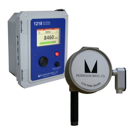
1218C External Input/Output Expansion Module
Installation, Operation, and Maintenance Instructions
The 1218C External Input/Output Expansion Module is an accessory to the 1218C Electronic Tank Gauge. This
module provides an additional 6 digital inputs, and 6 relay outputs when connected to a 1218C Electronic Tank
Gauge
!
Failure to follow any or all of the warnings and instructions in this document could result in a hazardous
liquid spill, which could result in property damage, environmental contamination, fire, explosion, serious
injury or death.
!
Le fait de ne pas se conformer à l'un ou l'autre des avertissements ou à l'une ou l'autre des directives
apparaissant dans ce document pourrait donner lieu à des déversements de liquides dangereux, lesquels
pourraient engendrer des dommages matériels, des risques de contamination environnementale,
d'incendie ou d'explosion, des blessures graves ou la mort.
Specifications
Input Power
100 – 240 VAC, 50/60Hz
Operating Temperature
-40°F to 140°F (-40°C to 60°C)
Enclosure Rating
NEMA 4X
Installation
!
Warnings
• Fire Hazard – Death or serious injury could result from spilled liquids.
• You must be trained to install or maintain this Electronic Tank Gauge. Stop now if you have not been trained.
• Any modification of this unit beyond what is outlined in this instruction will void product warranty.
• For your safety, it is important to follow local, state, federal and/or OSHA rules that apply to working
inside, above, or around the storage tank and piping area. Use all personal protective equipment required for
working in the specific environment.
• Tanks could be under pressure. Vapors could be expelled from tank vents, piping, valves or fittings while
performing maintenance. Vapors could catch fire or cause an explosion. Avoid sparks, open flame, or hot
tools when working on tank system.
• Use a dampened cloth when cleaning the alarm enclosure to prevent static buildup and discharge.
• In the event of malfunction, contact Morrison Bros. Co. Customer Service.
rev. 03-08-18
Digital Inputs (6)
Dry Contact (DI to GND) – ON: Closed / OFF: Open
Relay Outputs (6)
2 Amp maximum at up to 250 VAC or 30 VDC
Maximum Wiring Distance
Ethernet – 330ft (CAT5e cable recommended)
Inputs – 500ft (22 AWG wire recommended)
Outputs – 500ft (18 AWG wire recommended
Morrison Bros. Co. ‑ Dubuque, IA ‑ 800‑553‑4840
1
1218C‑0197 PP
Advertisement

Related Manuals for Morrison Bros. co. MOXA 1218C


Summary of Contents for Morrison Bros. co. MOXA 1218C
- Page 1 1218C External Input/Output Expansion Module Installation, Operation, and Maintenance Instructions The 1218C External Input/Output Expansion Module is an accessory to the 1218C Electronic Tank Gauge. This module provides an additional 6 digital inputs, and 6 relay outputs when connected to a 1218C Electronic Tank Gauge Failure to follow any or all of the warnings and instructions in this document could result in a hazardous liquid spill, which could result in property damage, environmental contamination, fire, explosion, serious...
- Page 2 AvErtISSEMEntS • Risque d’incendie – Un déversement de liquide pourrait entraîner des blessures graves ou la mort. • Vous devez avoir reçu une formation pour installer cette jauge de réservoir électronique ou en assurer la maintenance. Arrêtez-vous immédiatement si vous n’avez reçu aucune formation à cet effet. • Toutes les modifications apportées à cette unité autres que celles indiquées dans ces directives engendreront l’annulation de la garantie du produit.
- Page 3 Figure 2— Digital Input connection to Dry Contact Output Figure 3—Digital Input wiring to Sinking Wet Contact Output (NPN) Figure 4—Digital Input wiring to Sourcing Wet Contact Output (PNP) Up to six relay outputs can be connected to AC or DC loads (see specifications section). The I/O Module does not provide power to the loads. The loads being driven must supply their own power. Figure 5 shows the proper connection of a relay output to a power source and load.
-
Page 4: Initial Configuration
IMPORTANT: To prevent premature failure of the relay contacts it is strongly recommended to use a fuse and transient voltage suppressor (e.g. varistor, TVS diode). See Figure 5 for details. Preparation Before starting the configuration process find the static IP address of the 1218C Electronic Tank Gauge and record this address below as it will be used during the configuration process. If the 1218C Console is using DHCP you will need to configure it with a static IP address before continuing. Refer to ‘Configuring Your 1218C’ of the ‘Steps to Configure the 1218C’ section in the ‘1218C Electronic Tank Gauge IOM’ for details on configuring a static IP address. Next you will need to obtain a static IP address for the I/O Module. Record this IP address below for reference throughout the configuration process. - Page 5 4. Start by configuring the ‘Network Settings’… a. Click on the ‘E1214-T’ device in the navigation pane on the left side of the screen to open the configuration page. If no devices were found verify the E1214-T lights for ‘Power’, ‘Ready’, and ‘Port’ are illuminated/flashing. See the “ioLogik E1200 Series User’s Manual” for help troubleshooting. b. Under ‘General Settings’ set the ‘Server Name’ and ‘Server Location’ and click ‘Submit’ to save the changes. These fields will help identify this device from other devices on the network.
-
Page 6: Operation
Le fait de ne pas se conformer à l’un ou l’autre des avertissements ou à l’une ou l’autre des directives apparaissant dans ce document pourrait donner lieu à des déversements de liquides dangereux, lesquels pourraient engendrer des dommages matériels, des risques de contamination environnementale, d’incendie ou d’explosion, des blessures graves ou la mort. - Page 7 Configuration Once the 1218C firmware is up-to-date, open a web browser and go to the 1218C configuration web page to begin configuring the operation of the I/O Module. 1. Expand the ‘External I/O’ section and set the ‘IP Address’ of the I/O Module (recorded above) and then set the ‘Status’ to ‘Enabled’. 2. Expand the ‘External Inputs’ section and select an External Input that is to be enabled… a. Set the ‘Name’ setting (up to 14 characters) b. Set the ‘Type’ setting (Normally Open or Normally Closed) c.
- Page 8 e. Set the ‘Status’ setting to ‘Enabled’ 5. Repeat the previous step for any other relays that are to be enabled. 6. Next, you must assign alarm sources to each of the previously configured External Relays. Click on the button to ‘Select alarm sources to trigger relay output activation’ 7. For each I/O Module Output (rows of table) select the desired alarm source(s) and click the ‘Save’ button to finish.
- Page 9 8. To use any of the previously configured External Inputs to trigger an internal 1218C relay output, expand the ‘Relay Outputs’ section and click on the button to ‘Select alarm sources to trigger relay output activation.’ 9. For each Internal Relay (rows of table) select the desired alarm source(s) and click the ‘Save’ button to finish. Morrison Bros. Co. ‑ Dubuque, IA ‑ 800‑553‑4840 rev. 03-08-18 1218C‑0197 PP...
- Page 10 10. To enable Email or Text notifications, expand the ‘Email Notifications’ section… a. Set the ‘Type’ setting (Email or Text) b. Set the ‘Email Address’ (make sure it is correct before proceeding) c. Set the ‘Input Alarms’ setting to ‘Enabled’ d. Set the ‘Email Status’ setting to ‘Enabled’ Verification After completing the configuration of the I/O Module you must verify that it is operating as intended. Start by verifying that the I/O Module is enabled and communicating properly with the 1218C. Open the status web page and verify that the ‘External Inputs’...
-
Page 11: Maintenance
Failure to follow any or all of the warnings and instructions in this document could result in a hazardous liquid spill, which could result in property damage, environmental contamination, fire, explosion, serious injury or death. Le fait de ne pas se conformer à l’un ou l’autre des avertissements ou à l’une ou l’autre des directives apparaissant dans ce document pourrait donner lieu à...
Need help?
Do you have a question about the MOXA 1218C and is the answer not in the manual?
Questions and answers