Morrison Bros. co. 918AC Series Installation, Operation And Maintenance Instructions
Hide thumbs
Also See for 918AC Series:
Advertisement
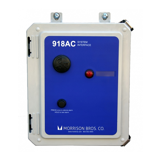
918AC Series Expansion Board
Installation, Operation, and Maintenance Instructions
The 918AC Expansion Board is designed to provide additional output configurability to the 918AC series
System Interface. The additional output configurations include: non-persist, auto-timeout with configurable
timeout value, and latching modes.
!
Failure to follow any or all of the warnings and instructions in this document could result in a hazardous
liquid spill, which could result in property damage, environmental contamination, fire, explosion, serious
injury or death.
Le fait de ne pas se conformer à l'un ou l'autre des avertissements ou à l'une ou l'autre des directives
!
apparaissant dans ce document pourrait donner lieu à des déversements de liquides dangereux, lesquels
pourraient engendrer des dommages matériels, des risques de contamination environnementale,
d'incendie ou d'explosion, des blessures graves ou la mort.
Contents
Installation..........................................................................................................................................1
Steps to Configure the 918AC Series System Interface Motherboard ..............................................2
Non-Persist Output Function ........................................................................................................ 2
Auto-Timeout Output Function ....................................................................................................3
Latching Mode Output Function .................................................................................................. 4
DIP Switch Configuration Tables ....................................................................................................6
Installation
1. Turn off the power to the 918AC Console.
2. Remove and retain the screw that is in the 918AC Motherboard, located to the left of the P101 connector and
below the reset button. It is the same location in which the standoff is installed in Figure 1.
3. Install the standoff provided in the kit into the same threads the screw was in, shown in Figure 1.
4. Install the 918AC Expansion Module by plugging it into the P101 connector on the 918AC Motherboard
with the orientation shown in Figure 1.
NOTE: If the 918AC Expansion Module does not fit correctly, do not force it. First, verify the
orientation of the expansion board shown in Figure 1. Then check that the motherboard version
is compatible. Compatible motherboards will have a pin removed corresponding to the keyed
pin on the expansion module.
Rev. 09-27-2022
Figure 1 - Standoff and Module Installation
Morrison Bros. Co. - Dubuque, IA - 800-553-4840
1
918AC-0160 PP
Advertisement
Table of Contents

Related Manuals for Morrison Bros. co. 918AC Series


Summary of Contents for Morrison Bros. co. 918AC Series
- Page 1 918AC Series Expansion Board Installation, Operation, and Maintenance Instructions The 918AC Expansion Board is designed to provide additional output configurability to the 918AC series System Interface. The additional output configurations include: non-persist, auto-timeout with configurable timeout value, and latching modes.
- Page 2 7. Once the 918AC Expansion Module is connected, configure the settings then press the reset button on the Module. The reset button will need to be pressed any time the settings are changed. Steps to Configure the 918AC Series System Interface Motherboard Non-Persistent Output Function The Non-Persistent relay output function allows each relay output to be reset to its normal condition once the active alarm has been acknowledged.
- Page 3 Auto-Timeout Output Function The Auto-Timeout relay output function allows each relay output to be reset to its normal condition after a configurable amount of time. The Timeout value can be adjusted in 3 minute increments from 3 to 30 minutes using the rotary switch.
- Page 4 5. Place the DIP switch Position Two in the “ON” position to configure the Motherboard to reset the channel 2 relay output when the auto-timeout timer has expired. Place the DIP switch Position Two in the “OFF” position to prevent the auto-timeout timer from changing the state of the channel 2 relay output. 6.
- Page 5 Figure 4 - Latching Mode Relay Output Configuration 1. Locate the four position, Latch Modes switch, SW 3, on the expansion board mezzanine (see Figure 4). 2. Use DIP switch Positions One and Two to set the Latching Mode for the channel 1 relay output a.
- Page 6 DIP Switch Configuration Tables Input Module Table 1 Expansion board SW1 – Non-Persistent Output Setting This output channel relay will be The alarm acknowledgement reset to its normal condition when has no effect on this output Position the alarm has been acknowledged Channel 1 Channel 1 Channel 2...
- Page 7 Table 4 Expansion board SW3 – Latch Modes Position Setting Channel 1 Latching Mode Disabled Channel 1 Latching Mode Enabled ‑ Input 2 Reset Channel 1 Latching Mode Enabled ‑ Input 3 Reset Channel 1 Latching Mode Enabled ‑ Input 4 Reset Position Setting Channel 2 Latching Mode Disabled...
Need help?
Do you have a question about the 918AC Series and is the answer not in the manual?
Questions and answers