
Related Manuals for Siemens FTI2001-U1


Summary of Contents for Siemens FTI2001-U1
- Page 1 FTI2001-U1 Fire terminal board Installation Mounting MP-UL 3.1 Smart Infrastructure A6V10315040_b_en_-- 2020-08-26...
- Page 2 Issued by: Siemens Industry, Inc. Smart Infrastructure 8 Fernwood Road Florham Park, NJ 07932 Tel. +1 973-593-2600 www.usa.siemens.com/fire Edition: 2020-08-26 Document ID: A6V10315040_b_en_-- A5Q00050753 © Siemens Industry, Inc., 2011 2 | 14 A6V10315040_b_en_--...
-
Page 3: Table Of Contents
Table of contents Fire terminal board FTI2001 ................Description...................... Installation ...................... Views ......................Pin assignments ..................... 1.4.1 Wiring overview ................1.4.2 X15 Supply output ................1.4.3 X17/X16 Supply input 1/2 ..............Indicators ......................Adjustment elements ..................Technical data ....................FCC Statement....................A6V10315040_b_en_-- 3 | 14... - Page 4 4 | 14 A6V10315040_b_en_--...
-
Page 5: Fire Terminal Board Fti2001
Fire terminal board FTI2001 Description 1 Fire terminal board FTI2001 1.1 Description The fire terminal board FTI2001 is used in the network terminal. The fire terminal board is supplied via a UL Fire Protective Signaling Listed, regulated power supply or via the DC 24 V AUX output of the periphery board of a fire control panel or voice alarm fire control panel. -
Page 6: Installation
Fire terminal board FTI2001 Installation ● Two supply inputs for external DC 24 V supply ● Two peripheral data bus connections to the PMI & mainboard and to the periphery options ● Two supervised power limited outputs rated at DC 24 V, 1 A each 1.2 Installation The fire terminal board FTI2001 is for the network terminal. - Page 7 Fire terminal board FTI2001 Installation Connector for operating unit via ribbon cable Connector for power supply output Vsys Connector for supply input Vsys 2 Connector for supply input Vsys 1 X400 Connector for the periphery bus (for options) 1. Install the fire terminal board (2) on the back box using the four fixing screws (3). 2.
-
Page 8: Views
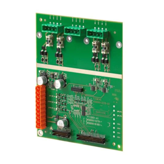
Fire terminal board FTI2001 Views 1.3 Views F203 F204 F202 F201 H204 H203 H202 H201 H205 H207 H206 X400 Figure 2: Printed circuit board view of fire terminal board FTI2001 8 | 14 A6V10315040_b_en_--... -
Page 9: Pin Assignments
Fire terminal board FTI2001 Pin assignments Element Des. Function Plugs and terminals Not used Plug connection to the PMI & mainboard Plug-in terminal for supply outputs (output 1 and 2) DC 24 V Plug-in terminal for supply input 2 (Vsys2) DC 24 V Plug-in terminal for supply input 1 (Vsys1) DC 24 V Not used X400 Plug connection for peripheral data bus... - Page 10 Fire terminal board FTI2001 Pin assignments PS 2 Output 2 Output 1 PS 1 Input 1 Input 2 Internal X400 Figure 3: Wiring for fire terminal board FTI2001 PS 1 Power supply input (necessary) PS 2 Power supply input for redundant supply Output 1 / Output Power supply outputs for peripherals Connector to X3 on PMI &...
-
Page 11: X15 Supply Output
Fire terminal board FTI2001 Indicators 1.4.2 X15 Supply output Designation Description GND 2 VSYS 2 System supply DC 24 V output (redundant supply) GND 1 VSYS 1 System supply output DC 24 V 1.4.3 X17/X16 Supply input 1/2 X16, plug-in terminal for supply input 2 (redundant supply input) Designation Description VSYS - 2... -
Page 12: Adjustment Elements
Fire terminal board FTI2001 Adjustment elements 1.6 Adjustment elements Switch Function Position Meaning S1-1 Supply input 1 'VSYS1' (X17) Input 1 is not used (default setting) Input 1 is used (supervised) S1-2 Supply input 2 'VSYS2' (X16) Input 2 is not used (default setting) Input 2 is used (supervised) 1.7 Technical data Supply input 1... -
Page 13: Fcc Statement
FCC Statement 2 FCC Statement WARNING Installation and usage of equipment is not in accordance with instructions manual Radiation of radio frequency energy Interference to radio communications ● Install and use equipment in accordance with instructions manual. ● Read the following information. This equipment generates, uses, and can radiate radio frequency energy and if not installed and used in accordance with the instructions manual, may cause interference to radio communications. - Page 14 Issued by Siemens Industry, Inc. Smart Infrastructure 8 Fernwood Road Florham Park, NJ 07932 +1 973-593-2600 www.usa.siemens.com/fire © Siemens Industry, Inc., 2011 Technical specifications and availability subject to change without notice. A6V10315040_b_en_--...
Need help?
Do you have a question about the FTI2001-U1 and is the answer not in the manual?
Questions and answers