Advertisement
Available languages
Available languages
INSTALLATION INSTRUCTIONS
C-AR-B-DD Series
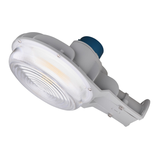
FIGURE 1
C-AR-B-DD SERIES-
DIRECT MOUNTED
CAUTIONS
IMPORTANT SAFEGUARDS
When using electrical equipment, basic safety
precautions should always be followed including the
READ AND FOLLOW ALL SAFETY
INSTRUCTIONS
1.
DANGER- Risk of shock- Disconnect power before
installation.
DANGER – Risque de choc – Couper l'alimentation
avant l'installation.
2. SUITABLE FOR WET LOCATIONS.
CONVIENT AUX EMPLACEMENTS MOUILLES.
3. SUITABLE FOR OPERATION IN AMBIENT NOT
EXCEEDING 50°C.
PEUT ETRE UTILISE A UNE TEMPERATURE
AMBIANTE N'EXCEDANT PAS 50°C.
4. INSTALL PHOTOCONTROL OR SHORTING PLUG.
INSTALLER UNE CELLULE PHOTOELECTRIQUE OU
UNE PRISE COURT-CIRCUITANTE.
5. CLASS 1 WIRING ONLY. When dimming cord provided
SAVE THESE INSTRUCTIONS FOR
FUTURE REFERENCE
DIRECT MOUNTING
1.
Install fixture cover plate to conduit using either knockout.
2.
Use fixture to mark the location for the lag bolts on
mounting surface.
3.
Install two lower lag bolts into mounting surface, allowing
the head of each bolt to remain 1/4" (6.4 mm) from
mounting surface.
4.
Wire black fixture lead to the incoming voltage supply
or Hot 1 lead and the white fixture lead to the incoming
neutral (Common) or Hot 2 lead. Attach bare copper or
green ground fixture lead to the incoming ground lead.
5.
If 0/1-10V dimming is used, connect the violet fixture lead
to the supply positive dimming lead and the gray fixture
following:
http://lighting.cree.com/warranty
LPN00833X0001A0 _A
Document:
Created By:
TMT
lead to the negative dimming lead.
If dimming is not be used, make sure the violet and gray
fixture leads are capped off.
NOTE: Dimming should only be used if the fixture is set to
60 W in Step 9 below.
6.
Slide fixture onto two lag bolts from Step 3 and install third
lag bolt in top slot of fixture. Secure all lag bolts.
7.
Secure cover plate with (2) Allen bolts, lock washers, and
flat washers. Position lock washer under bolt head and flat
washer between lock washer and cover plate. Discard arm
bracket.
8.
Install the photo-control by aligning the arrow on the top
of the photo-control with the arrow on the photo-control
socket and inserting pins into the socket. Twist photo-
control clockwise. (Photocontrol must be rotated at least
1/8 turn to properly lock in place). See Figure 3.
NOTE: Improper installation of the photo-control may result
in damage to the photo-control.
9.
Remove threaded plug from top surface of fixture and
position toggle switch for desired wattage (See Figure 4
on next page):
• I = 29W
• II = 40W
• III = 60W
10. Replace plug removed in Step 9 above.
FIGURE 2- Items Included with Fixture
FIGURE 3- Photo-control Installation
|
1-800-236-6800
7-16-2020
Date
Advertisement
Table of Contents

Related Manuals for e-conolight C-LITE C-AR-B-DD Series


Summary of Contents for e-conolight C-LITE C-AR-B-DD Series
- Page 1 LPN00833X0001A0 _A 7-16-2020 Document: Date INSTALLATION INSTRUCTIONS Created By: C-AR-B-DD Series lead to the negative dimming lead. If dimming is not be used, make sure the violet and gray fixture leads are capped off. NOTE: Dimming should only be used if the fixture is set to 60 W in Step 9 below.
-
Page 2: Installation Instructions
LPN00833X0001A0 _A 7-16-2020 Document: Date INSTALLATION INSTRUCTIONS Created By: C-AR-B-DD Series Feed (Customer Supplied) Ground wire up through arm. FIGURE 4- Toggle Switch Feed black and white fixture wires down through arm. Plug Insert long end of arm into opening in fixture, above arm bracket loosened in Step 1. -
Page 3: Medidas De Seguridad Importantes
Documento: LPN00833X0001A0 _A Fecha 7-16-2020 INSTRUCCIONES DE INSTALACIÓN Creado por: Serie C-AR-B-DD suministro y el cable gris de la luminaria al cable negativo de atenuación. Si no se utiliza atenuación, asegúrese de cubrir los cables morado y gris de la luminaria. NOTA: Solo se debe usar atenuación si la luminaria se confi... - Page 4 Documento: LPN00833X0001A0 _A Fecha 7-16-2020 INSTRUCCIONES DE INSTALACIÓN Creado por: Serie C-AR-B-DD cabeza de hongo. FIGURA 4: Interruptor conmutador Pase el cable de tierra (suministrado por el cliente) hacia arriba a través del brazo. Pase los cables negro y blanco de la luminaria hacia abajo a través del brazo.
-
Page 5: Mesures De Sécurité Importantes
Document : LPN00833X0001A0 _A Date 16-07-2020 INSTRUCTIONS D’INSTALLATION Créé par : Série C-AR-B-DD fi l gris du luminaire au fi l de gradation négatif. Si la gradation n'est pas utilisée, bouchez les fi ls gris et violet du luminaire. REMARQUE : La gradation ne doit être utilisée que si le luminaire est confi... -
Page 6: Instructions D'installation
Document : LPN00833X0001A0 _A Date 16-07-2020 INSTRUCTIONS D’INSTALLATION Créé par : Série C-AR-B-DD montage. Réglez dans la direction désirée et serrez les FIGURE 4 - Interrupteur à bascule boulons de carrosserie. Acheminez le fi l de terre (fourni par le client) vers le haut dans le bras.
Need help?
Do you have a question about the C-LITE C-AR-B-DD Series and is the answer not in the manual?
Questions and answers