Subscribe to Our Youtube Channel
Summary of Contents for Sunways STS-1KTL-S
- Page 1 Grid-connected PV Inverter Single Phase Single MPPT User Manual STS-1K/1.5K/2K/2.5K/3K/3.3KTL-S Ningbo Sunways Technologies Co., Ltd.
-
Page 2: Table Of Contents
CONTENTS 1. Preface ........................5 1.1 Overview ......................5 1.2 Target Groups ....................5 2. Safety Instructions ....................5 2.1 Safety Notes ....................5 2.2 Statement ......................5 2.3 Important Safety Matters ................6 2.4 Symbols Explanation ..................7 3. Product Introduction ...................9 3.1 Basic Features ....................9 3.2 Appearance Introduction ................10 3.3 Display Interface ..................12 3.4 Packing List ....................13 4. - Page 3 2.2 Statement Ningbo Sunways technologies Co., Ltd. has the right not to undertake quality assurance in any of the following circumstances: 2.2.1 Damages caused by irregular transportation.
-
Page 4: Important Safety Matters
2.4 Symbols Explanation 2.2.2 Damages caused by incorrect storage, installation or use. 2.2.3 Damages caused by installation and use of equipment by non-professionals or untrained This chapter mainly elaborates the symbols displayed on the inverter, nameplate and packing personnel. box. 2.2.4 Damages caused by failure to comply with the instructions and safety warnings in the 2.4.1 Symbols on the Inverter products and documents. -
Page 5: Product Introduction
3.1.3 Applicable grid type The applicable grid types for the Sunways STS 1~3.3kW-S series are TN-S, TN-C, TN-C-S and TT. When applied to the TT grid, the voltage of N to PE should be less than 30V. See Figure 3-1 for Stacked layers. -
Page 6: Appearance Introduction
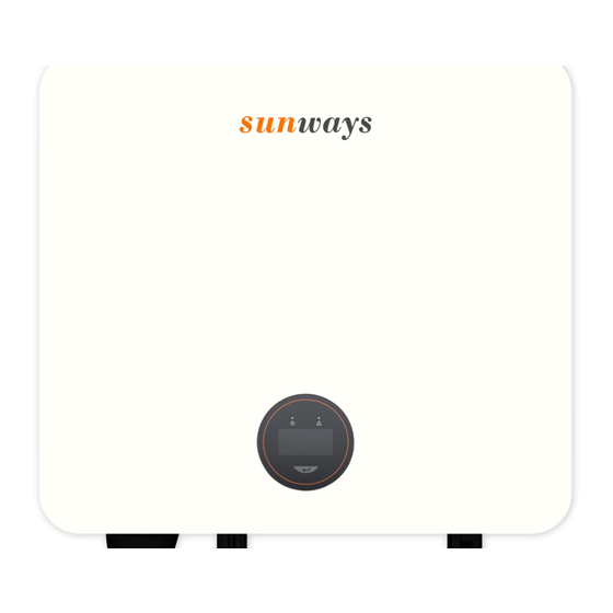
3.2 Appearance Introduction 3.2.3 Inverter bottom view, as shown in Figure 3-4: 3.2.1 Inverter front view, as shown in Figure 3-2: 327mm Logo DC Switch (Optional) Com1 Port Com2 Port (Optional) DC Input Terminal Back Rail Display Figure 3-4 Bottom view 3.2.4 Inverter back view, as shown in Figure 3-5: Figure 3-2 Front view 3.2.2 Inverter side view, as shown in Figure 3-3:... -
Page 7: Product Installation
4.1 Selection of Installation Location Slow flashing Inverter powered on, waiting for the grid connection. The Sunways STS 1~3.3kW-S series is designed with IP65 protection for indoor and outdoor Power Indicator installations. When selecting an inverter installation location, the following factors should be Quick flashing Inverter detected grid power and entered self-test status. -
Page 8: Mounting The Inverter
4.2 Mounting the Inverter 4.2.1 Wall bracket installation Dimensions of wall bracket, see Figure 4-4: Figure 4-1 Recommended installation location 220mm 16mm Warning Do not put flammable and explosive articles around the inverter. 110mm 110mm 4.1.2 The requirements for inverter installation spacing are shown in Figure 4-2: 10mm 300mm 300mm... -
Page 9: Electrical Connection
Do not use other brands or other types of terminals other than the terminals in Attention the accessory package. Sunways has the right to refuse all damages caused by the mixed-use of terminals. Moisture and dust can damage the inverter, ensure the cable gland is securely Attention tightened during installation. - Page 10 The Sunways 1~3.3kW-S series single phase inverter applies to the single-phase power grid with a voltage of 220/230V and a frequency of 50/60Hz. The recommended cable and AC breaker for the Sunways STS 1~3.3kW-S series single phase inverter are shown in the following table:...
- Page 11 2) According to the table above, select an appropriate cable, peel the insulation sleeve of AC 5) Connect the AC connector to the inverter AC terminal, and the slight click represents the cable off for 50mm, and peel off the end of L /PE / N wires for 8mm, as shown in Figure 4-14: connection is in the place.
-
Page 12: Monitoring Device Installation
Figure 4-20: 4.4 Monitoring Device Installation Sunways STS 1~3.3kW-S series single phase inverter supports WiFi, GPRS and RS485 communication, you can choose according to your specific needs. Plug the WiFi or GPRS module into the COM1 port in the bottom of inverter by following the... - Page 13 AS/ Anti-reverse or power limit solution, wiring instructions and configuration, please contact NZS4777.2:2015 standard. Port 2 Sunways after-sales at service@sunways-tech.com. 3.Sunways inverter is fully complied with all DRM. The 6pin connector is used for DRM DRM3/7 4.5.4 Connection steps: connection.
-
Page 14: System Layout Of Units Without Integrated Dc Switch
Insulator ring Inverter Grid 20-25mm DC Switch DC INPUT AC OUTPUT Port 1 Port 2 AC Breaker 20-25mm Port 3 Screw cap Metal plate Sealing ring 3/6pin connector To grounding electrode Figure 4-22 Figure 4-24 5. Start and Stop Start the Inverter When starting the inverter, follow these steps: 1) Turn on the AC breaker first (close the AC circuit breaker). -
Page 15: General Operation
6. General Operation 6.2 Auto-Test This function is disabled by default, and only will be functional in the safety code of Italy. 6.1 Display Operation Short press the button several times until “Auto Test CEI 0-21” displays on the screen, press When the inverter is turned on, the following interfaces will be displayed on the OLED display, and hold the button 3 seconds to activate “Auto Test”. -
Page 16: Troubleshooting
7.1 Fault Messages Risk of inverter damage or personal injury due to incorrect service! Sunways STS 1~3.3kW-S series single phase inverter is designed in accordance with grid Always keep in mind that the inverter is powered by dual sources: PV strings and utility grid. -
Page 17: Technical Parameters
8. Technical Parameters STS- STS- STS- STS- STS- STS- STS- STS- STS- STS- STS- STS- Model Model 1KTL-S 1.5KTL-S 2KTL-S 2.5KTL-S 3KTL-S 3.3KTL-S* 1KTL-S 1.5KTL-S 2KTL-S 2.5KTL-S 3KTL-S 3.3KTL-S* Start-up Voltage (V) Max. Efficiency 97.3% 97.3% 97.5% 97.5% 97.5% 97.5% Max. - Page 18 Address: No. 1, Second Road, Green Industrial Zone, Chongshou Town, Cixi City, ZheJiang Province, PEOPLE’S REPUBLIC OF CHINA Website: www.sunways-tech.com Service Mail: service@sunways-tech.com Hotline: +86 400-9922-958...


Need help?
Do you have a question about the STS-1KTL-S and is the answer not in the manual?
Questions and answers