
Related Manuals for Bailey infi90 IMMFP03


Summary of Contents for Bailey infi90 IMMFP03
- Page 1 E96-203 ® ® Multi-Function Processor Module (IMMFP03/IMMFP03B) Process Control and Automation Solutions from Elsag Bailey Group...
- Page 2 The information contained in this document is subject to change without notice. Elsag Bailey, its affiliates, employees, and agents, and the authors and contributors to this publication specif- ically disclaim all liabilities and warranties, express and implied (including warranties of merchantability and...
- Page 3 Preface The IMMFP03 and IMMFP03B Multi-Function Processor Mod- ules are powerful stand-alone process controllers for use in complex control applications. They have the processing speed and storage capabilities necessary for advanced control appli- cations. The IMMFP03 module is a user-configurable device that receives process input and output through a variety of analog and digital I/O modules.
- Page 4 Elsag Bailey Process Autom ation List of Effective Pages Total number of pages in this instruction is 82, consisting of the following: Page No. Change Date Preface Original List of Effective Pages Original iii through viii Original 1-1 through 1-6...
- Page 5 Safety Summary GENERAL Equipment Environment WARNINGS All components, whether in transportation, operation or storage, must be in a noncorrosive environment. Electrical Shock Hazard During Maintenance Disconnect power or take precautions to insure that contact with energized parts is avoided when servicing. Special Handling This module uses electrostatic sensitive devices.
- Page 6 Elsag Bailey Process Autom ation Sommaire de Sécurité AVERTISSEMENTS Environnement de l’équipement D’ORDRE Ne pas soumettre les composants à une atmosphère corrosive GÉNÉRAL lors du transport, de l’entreposage ou l’utilisation. Possibilité de chocs électriques durant l’entretien Débrancher l’alimentation ou prendre les précautions pour éviter tout contact avec des composants sous tension durant l’entretien.
-
Page 7: Table Of Contents
Table of Contents Page SECTION 1 - INTRODUCTION....................1-1 OVERVIEW ......................1-1 INTENDED USER .....................1-1 HARDWARE DESCRIPTION ..................1-1 Faceplate ......................1-2 Circuit Board .....................1-3 HARDWARE APPLICATION ..................1-3 FEATURES .......................1-3 INSTRUCTION CONTENT..................1-3 HOW TO USE THIS INSTRUCTION ................1-4 GLOSSARY OF TERMS AND ABBREVIATIONS ............1-4 REFERENCE DOCUMENTS ..................1-5 NOMENCLATURE .....................1-5 SPECIFICATIONS .....................1-6... - Page 8 Elsag Bailey Process Automation Table of Contents (continued) Page SECTION 4 - OPERATING PROCEDURES ................4-1 INTRODUCTION ...................... 4-1 MFP MODULE START-UP..................4-1 MFP MODULE LEDs ....................4-1 Front Panel LEDs ....................4-2 Red/Green Status LED ..................4-3 MFP MODULE STOP/RESET SWITCH ..............4-3 MFP MODULE MODES OF OPERATION ..............
- Page 9 Table of Contents (continued) Page APPENDIX B - ON-LINE CONFIGURATION (continued) OPERATION ......................B-1 Backup Cycle ....................B-3 Primary Cycle ....................B-6 APPENDIX C - NTMP01 CONFIGURATION ................C-1 INTRODUCTION ...................... C-1 APPENDIX D - NIMP01 AND NIMP02 CONFIGURATION ............. D-1 INTRODUCTION ......................
- Page 10 Elsag Bailey Process Automation List of Tables Title Page 1-1. Glossary of Terms and Abbreviations ..............1-4 1-2. Reference Documents .................... 1-5 1-3. Nomenclature ......................1-5 1-4. Specifications ......................1-6 3-1. Dipswitch UUB0 Settings for MFP Operation ............3-4 3-2.
-
Page 11: Section 1 - Introduction
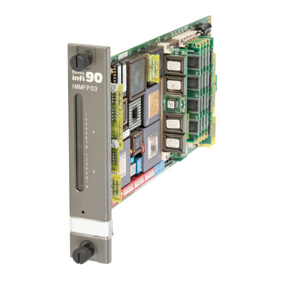
(especially function codes) would help when configuring the MFP module. HARDWARE DESCRIPTION The IMMFP03 Multi-Function Processor Module consists of a circuit board and faceplate. ® INFI 90 is a registered trademark of Elsag Bailey Process Automation. OVERVIEW I-E96-203C 1 - 1... -
Page 12: Faceplate
Besides locking the module in place, the faceplate also protects the circuit components and promotes proper air flow within the cabinet. ® INFI-NET is a registered trademark of Elsag Bailey Process Automation. HARDWARE DESCRIPTION 1 - 2 I-E96-203C... -
Page 13: Circuit Board
(SRAM), read only memory (ROM), a microprocessor running at 32 megahertz, direct memory access (DMA) circuits, Elsag Bailey custom bus circuits and various support circuitry. The board attaches to the faceplate with two screws. The module assembly occupies one slot in a module mounting unit. -
Page 14: How To Use This Instruction
GLOSSARY OF TERMS AND ABBREVIATIONS Table contains those terms and abbreviations that are unique to Elsag Bailey or have a definition that is different from standard industry usage. Table 1-1. Glossary of Terms and Abbreviations Term Definition I/O Expander Bus Parallel communication bus between the control and I/O modules. -
Page 15: Reference Documents
Termination unit cable (PVC) NKTU02 Termination module cable (PVC) NKTU11 Termination unit cable (non-PVC) NKTU12 Termination module cable (non-PVC) NTMP01 Multi-function processor module termination unit ® Network 90 is a registered trademark of Elsag Bailey Process Automation. REFERENCE DOCUMENTS I-E96-203C 1 - 5... -
Page 16: Specifications
Elsag Bailey INTRODUCTION Process Autom ation SPECIFICATIONS Table lists the specifications for the IMMFP03 and IMMFP03B Multi-Function Processor Modules, and IMMPI01 Multi-Function Processor Interface Module. Table 1-4. Specifications Property Characteristic/Value IMMFP03/IMMFP03B Microprocessor 32-bit processor running at 32 MHz Memory All memory has 32-bit data path... -
Page 17: Section 2 - Description And Operation
SECTION 2 - DESCRIPTION AND OPERATION INTRODUCTION This section explains the functionality of the IMMFP03 Multi- Function Processor Module and IMMPI01 Multi-Function Processor Interface Module using block diagrams and text. Block diagrams divide the operation of the multi-function processor (MFP) and multi-function processor interface (MPI) modules into a series of functional blocks. -
Page 18: Mfp Module Circuitry
Elsag Bailey DESCRIPTION AND OPERATION Process Autom ation module (MPI), interfaces the MFP module via a 60-pin ribbon cable that passes through a slot in the MFP module and plugs into appropriate headers on each board. The physical connection to the RS-232-C ports is accomplished through an NTMP01 Multi-Function Processor Termination Unit or NIMP01 Multi-Function Processor Termination Module. -
Page 19: Clock And Real Time Clock
I/O expander bus, the dual redundancy link, the IISAC01 Analog Control Station or NDCS03 Digital Control Station serial link and Controlway. Elsag Bailey-designed chips control DMA activity. The DMA process greatly reduces the amount of work the microprocessor needs to do when making data moves. -
Page 20: Controlway
Elsag Bailey DESCRIPTION AND OPERATION Process Autom ation it greatly increases the speed of the MFP module by not over- loading the microprocessor with the work associated with data moves. The microprocessor does not have to execute data moves and is free to do other tasks. -
Page 21: I/O Expander Bus
I/O Expander Bus The I/O expander bus interface is implemented using an Elsag Bailey-designed integrated circuit. The microprocessor can select one of two modes of operation: DMA or auto mode. The MFP software selects the mode of operation for the I/O expander bus. -
Page 22: Mpi Module Circuitry
Elsag Bailey DESCRIPTION AND OPERATION Process Autom ation The MPI module connects to an NTMP01 Multi-Function Pro- cessor Termination Unit. I/O signals enter or leave the MPI module through an NKTU01 or NKTU11 termination unit cable connected to an NTMP01 termination unit. Another... -
Page 23: Station Link
DESCRIPTION AND OPERATION Station Link The station link is a set of drivers and receivers on the MPI module. Station communication originates from a DUART cir- cuit on the MFP module. This link controls the serial commu- nication between the MFP module and the digital control stations. -
Page 24: Section 3 - Installation
SPECIAL HANDLING Observe these steps when handling electronic circuitry: NOTE: Always use Elsag Bailey's field static kit (part number 1948385 1 - consisting of two wrist straps, ground cord assembly, alligator clip and static dissipative work surface) when working with the modules. -
Page 25: Unpacking And Inspection
UNPACKING AND INSPECTION 1. Examine the hardware immediately to verify that it has not been damaged in transit. 2. Notify the nearest Elsag Bailey sales office of any such damage. 3. File a claim for any damage with the transportation com- pany that handled the shipment. -
Page 26: Dipswitch Uub0 - Module Address
INSTALLATION MODB CR17 BAUD OPTION RATE DIAGNOSTICS SCSI SW ITCH SW ITCH SW ITCH SW ITCH 2MBIT SW 6 SW 4 SW 1 SW 2 SW 3 1MBIT 4MBIT 1 2 3 4 5 6 7 8 1 2 3 4 5 6 7 8 1 2 3 4 5 6 7 8 1 2 3 4 5 6 7 8 16 15 14 13 12 11 10 9... -
Page 27: Dipswitch Umb1 - Module Options And Diagnostics
Elsag Bailey INSTALLATION Process Autom ation Table 3-1. Dipswitch UUB0 Settings for MFP Operation User Pole Setting Function Setting Normal run Enable diagnostics using dipswitch UMB1 Not used - do not change setting Controlway (1 Mbaud) -30 VDC operation or module bus (83.3 kbaud) used... -
Page 28: Special Operations
INSTALLATION Table 3-3. Dipswitch UMB1 Options and Diagnostics (continued) User Pole Setting Function Setting Normal operation. Compact configuration. The compact configuration function moves configured function blocks to the top of the NVRAM while moving free space to the bottom. To enable this function, OPEN the pole and insert the module into the module mounting unit. -
Page 29: Dipswitch Lmb2 - Module Options And Scsi Bus Address
Elsag Bailey INSTALLATION Process Autom ation Table 3-4. Dipswitch UMB1 Special Operation Settings (continued) Special Dipswitch Pole Description Operation 1 2 3 4 5 6 7 8 1 0 0 0 0 1 0 1 Permit segment modification (allows change to segment scheme configured with function code 82, specification S1). -
Page 30: Dipswitch Llb3 - Module Options
This setting must be used if dipswitch UUB0 selects Controlway. NOTES: 1. Used by Bailey Controls Company service personnel. The J1 setting does not affect the module during normal operation. 2. Jumper J2 must be set to 4-1 for all firmware levels. -
Page 31: Hw Setup Socket Jumper
Elsag Bailey INSTALLATION Process Autom ation HW SETUP Socket Jumper The HW SETUP socket defines the number of SRAM memory banks installed and selects wait states for ROM, NVRAM and SRAM memory. Refer to Table for the jumper settings. Table 3-7. HW SETUP Socket Jumper Settings... -
Page 32: Preparing The Module Mounting Unit
INSTALLATION Refer to NIMP01, NIMP02 and NTMP01 product instructions for information on how to select handshake signals on the termination unit or module. CTSB/DIGIN 1 (+) CTSB (+) P3-25 DUART DIGIN 1 (+) DUART CTSB/DIGIN 1 (-) CTSB (-) P3-10 DUART +5 VDC DIGIN 1 (-) -
Page 33: Dipshunts
Elsag Bailey INSTALLATION Process Autom ation Dipshunts Disconnect power before installing dipshunts on the module WARNING mounting unit backplane. Failure to do so will result in con- tact with cabinet areas that could cause severe or fatal shock. Interrompez l'alimentation avant d'installer des dipshunts sur le fond de panier du châssis de montage des modules. -
Page 34: Installing The Termination Unit Or Module And Field Wiring
INSTALLATION 2. Attach (in the same sequence) the other end of the cable to the bottom three tabs on the lower left of the next module mounting unit backplane. NOTE: Due to high speed transaction constraints, a maximum of eight related (Controlways linked by cable) module mounting units can be installed in one cabinet. -
Page 35: Installing The Modules
Elsag Bailey INSTALLATION Process Autom ation INSTALLING THE MODULES The following steps explain how to install the MFP module with an MPI module. If your application uses only an MFP module, ignore the steps involving the MPI module. Never operate the MFP module with the machine fault timer circuit disabled (jumper pins connected). - Page 36 INSTALLATION then turn green. If it does not, refer to the troubleshooting section. To install MFP and MPI modules: 1. Install the high density 60-pin ribbon cable (Table 8-1) that connects the MFP module to the MPI module. Connect one end of the cable to connector P5 on the MFP module. Connect the other end of the ribbon cable to connector P6 on the MPI module.
-
Page 37: Section 4 - Operating Procedures
SECTION 4 - OPERATING PROCEDURES INTRODUCTION The first part of this section explains what happens during start-up, the LED indicators and what they mean, and how to stop or reset the module. The last part explains the three modes of operation. MFP MODULE START-UP When power is applied to the IMMFP03 Multi-Function Pro- cessor Module, the module does an internal check, checks its... -
Page 38: Front Panel Leds
Elsag Bailey OPERATING PROCEDURES Process Autom ation IMMFP03 RED/GREEN STATUS LED GROUP A LEDs GROUP B LEDs STOP/RESET SWITCH TP25212B Figure 4-1. MFP Front Panel Front Panel LEDs Group A LEDs display the pass and fail counts when the module is in diagnostic mode. Group B LEDs display codes if a module error occurs during normal operation. -
Page 39: Red/Green Status Led
OPERATING PROCEDURES Red/Green Status LED The status LED is a red/green LED. It shows MFP operating condition. There are four possible states. No power to the module or the module is powered and jumper J4 is installed (machine fault timer disabled). The machine fault timer circuit must be enabled. -
Page 40: Mfp Module Modes Of Operation
Elsag Bailey OPERATING PROCEDURES Process Autom ation Once the module is stopped, pressing the switch again resets the module. Use the reset mode to: Reset the default values to the power up values. • Recover from a module time-out or operator-initiated stop. -
Page 41: Mpi Module Operation
OPERATING PROCEDURES MPI MODULE OPERATION Upon proper installation, the IMMPI01 Multi-Function Pro- cessor Interface Module (MPI) is ready for operation. The MPI module waits for the MFP module to give it a command to execute; it does nothing on its own. MPI MODULE LED There is one yellow LED on the faceplate of the MPI module (Fig. -
Page 42: Section 5 - Troubleshooting
Corrective Action 8 7 6 5 4 3 2 1 0 0 0 0 0 0 0 1 NVRAM checksum error Initialize NVRAM. If error recurs call Bailey field service. 0 0 0 0 0 0 1 0 Analog input calibration Check I/O module error. - Page 43 Set addresses the same. addresses are different 0 0 0 1 0 0 1 1 ROM checksum error Contact Bailey field service. 0 0 0 1 0 1 0 0 MFP set for INFI-NET/ Reformat MFP module. Superloop but in a Plant Loop...
-
Page 44: Other Mfp Module Conditions
Restart MFP module. If error recurs, replace MFP module. 0 0 1 1 1 0 0 0 Board level hardware error Contact Bailey field service. 0 0 1 1 1 1 1 1 Normal stop None. 0 1 0 0 0 0 0 0... -
Page 45: Mfp Troubleshooting Flowchart (Serial Port)
Elsag Bailey TROUBLESHOOTING Process Autom ation START RS-232-C LINE ERRORS DONE ON MFP LEDs (CODE 15)? +24 VDC REFER TO TMP/IMP CONNECTED TO OPEN ON INSTRUCTIONS TO TU/TM? TU/TM? CONNECT POW ER REPLACE F1 CHECK POW ER W ITH 1.0 A MEASURE CABLING TO TU/TM. -
Page 46: Card Edge Connectors
TROUBLESHOOTING START STATUS STATUS LED STATUS LED STATUS LED LED OFF? RED? GREEN? ORANGE? TURN ON POW ER ON? ERROR CODE POW ER DONE REMOVE MACHINE DISPLAYED? FAULT TIMER JUMPER FROM MFP MODULE PERFORM SEAT MFP CORRECTIVE MODULE SEATED MODULE IN MMU ACTION APPLICABLE IN MMU? BACKPLANE... -
Page 47: Mfp Connector P2 Pin Assignments
Elsag Bailey TROUBLESHOOTING Process Autom ation Table 5-4. MFP Connector P2 Pin Assignments Signal Signal Data bit 1 Data bit 0 Data bit 3 Data bit 2 Data bit 5 Data bit 4 Data bit 7 Data bit 6 Bus clock - BCLK... -
Page 48: Diagnostics
TROUBLESHOOTING Table 5-8. MPI Connector P3 Pin Assignments Signal Signal SAC/DCS link A (–) SAC/DCS link A (+) SAC/DCS link B (–) SAC/DCS link B (+) 3 - 6 Unused 18 - 21 NC Receive data A (–) Receive data A (+) Receive data B (–) Receive data B (+) Clear to send A (–) -
Page 49: Dipswitch Selection
Elsag Bailey TROUBLESHOOTING Process Autom ation 3. There must be continuity between the DSO and MFP modules on the I/O expander bus (i.e., I/O expander bus dip- shunts inserted with straps intact between the DSO and MFP modules). The modules do not need to be in adjacent slots. -
Page 50: Diagnostic Tests
TROUBLESHOOTING Refer to Table 5-10 for test ID values. Pole one selects a spe- cial operations feature. When enabled, the MFP module will halt test execution whenever the selected test detects an error. The number of the failing test is displayed on the group B LEDs (Fig. -
Page 51: Led Display
Elsag Bailey TROUBLESHOOTING Process Autom ation Table 5-10. Diagnostic Tests (continued) Test Name Test-ID Description I/O expander bus Arms assassin circuit and allows I/O expander bus clock to stall. assassin circuit halt test NVRAM retention Stores known data pattern in NVRAM. -
Page 52: Immfp03 Module Status Summary
TROUBLESHOOTING On module reset, all front panel LEDs turn on. Next, the MFP module reads the dipswitches, executes the selected test and displays the result on the group A and group B LEDs. Group B LEDs display the test number on LEDs one through six. - Page 53 Elsag Bailey TROUBLESHOOTING Process Autom ation Table 5-12. Field Descriptions of the MFP Status Report Byte Field Value Description — Error summary (0 = good, 1 = errors) MODE — Module mode (00 = configuration, 01 = error, 11 = execute) MODULE TYPE —...
-
Page 54: Section 6 - Maintenance
éclaboussures de solvant pourraient causer des blessures aux yeux. The reliability of any stand-alone product or control system is affected by the maintenance of the equipment. Elsag Bailey recommends that all equipment users practice a preventive maintenance program that will keep the equipment operating at an optimum level. -
Page 55: Equipment And Tools Required
Elsag Bailey MAINTENANCE Process Autom ation Table 6-1. Preventive Maintenance Schedule Task Frequency Check cabinet air filters. Clean or replace them as necessary. Check the air filter more 3 months frequently in excessively dirty environments. Check cabinet and MFP module for dust. Clean as necessary using an antistatic vacuum. -
Page 56: Edge Connector Cleaning
MAINTENANCE vacuum cleaner. Another method of washing the printed cir- cuit board is: 1. Clean the printed circuit board by spraying it with isopro- pyl alcohol (99.5% electronic grade) or wiping the board with a foam tipped swab wetted in isopropyl alcohol. 2. -
Page 57: Section 7 - Repair/Replacement Procedures
SECTION 7 - REPAIR/REPLACEMENT PROCEDURES INTRODUCTION Repair procedures are limited to module replacement. If the IMMFP03 Multi-Function Processor Module or IMMPI01 interface module fails, remove and replace it with another. Verify that firmware revision levels match and that the replacement module switch and jumper settings are the same as those of the failed module. -
Page 58: Termination Unit Or Module Replacement Procedures
Elsag Bailey REPAIR/REPLACEMENT PROCEDURES Process Autom ation To replace the MPI module: 1. Turn the two latching screws on the MPI and MFP mod- ules ½-turn to release them. 2. Grasp the screws and slide out both modules. 3. Disconnect the auxiliary I/O ribbon cable from connector P6 on the MPI module. -
Page 59: Section 8 - Support Services
SECTION 8 - SUPPORT SERVICES INTRODUCTION Bailey Controls Company is ready to help in the use and repair of its products. Contact the nearest sales office to make requests for sales, applications, installation, repair, overhaul and maintenance contract services. REPLACEMENT PARTS AND ORDERING INFORMATION When making repairs, order replacement parts from a Bailey Controls Company sales office. -
Page 60: Appendix A - Quick Reference Material
APPENDIX A - QUICK REFERENCE MATERIAL INTRODUCTION This appendix provides several tables for quick reference purposes. Tables through show the dipswitch set- tings for dipswitches UUB0, UMB1 and LLB3. Table shows the jumper settings for jumpers J1, J2, J4 and J5. Table shows the jumper settings for the HW SETUP socket. -
Page 61: Dipswitch Umb1 Special Operation Settings
Elsag Bailey QUICK REFERENCE MATERIAL Process Autom ation Table A-3. Dipswitch UMB1 Options and Diagnostics (continued) Pole Setting Function Normal operation Compact configuration function Normal operation Initialize NVRAM (erase configuration) memory. This pole must remain CLOSED for normal operation. Primary MFP module Redundant MFP module NOTES: 0 = CLOSED or ON, 1 = OPEN or OFF. -
Page 62: Jumpers J1, J2, J4 And J5 Settings
This setting must be used if dipswitch UUB0 selects the Controlway. NOTES: 1. Used by Bailey Controls Company service personnel. The J1 setting does not affect the module during normal operation. 2. Jumper J2 must be set to 4-1 for all firmware levels. - Page 63 Elsag Bailey QUICK REFERENCE MATERIAL Process Autom ation Table A-8. Front Panel LED Error Codes (continued) Code Condition 8 7 6 5 4 3 2 1 0 0 0 1 0 0 0 1 Error during write to nonvolatile memory...
- Page 64 QUICK REFERENCE MATERIAL Table A-9. Other LED Conditions Condition Problem Status No power, improper module seating, jumper J4 installed or defective module Module not properly seated or defective Green None - normal operation Orange Jumper J4 installed Group B No power, improper module seating, or defective module None - indicates primary module Group B No power, improper module seating, or defective module...
-
Page 65: Appendix B - On-Line Configuration
APPENDIX B - ON-LINE CONFIGURATION INTRODUCTION Using on-line configuration in conjunction with redundant IMMFP03 and IMMFP03B Multi-Function Processor Modules enables making configuration changes without affecting the primary MFP module or interrupting the control process. In redundant MFP module configurations, the primary MFP module executes the process control logic while the backup MFP module tracks the configuration of the primary. - Page 66 Elsag Bailey ON-LINE CONFIGURATION Process Autom ation Management command system. • Engineering work station. • NOTE: Care must be exercised to avoid deleting blocks or adding blocks in the middle of existing ones. (Refer to the notes at the end of Step 2 in Table for further explanation).
-
Page 67: Backup Cycle
ON-LINE CONFIGURATION backup MFP module will always refer to the original backup MFP module and the term primary MFP module will always refer to the original primary MFP module. When the roles are reversed for either unit, their status is carefully noted. Backup Cycle The step numbers in this cycle correspond to the status of Figure B-1. - Page 68 Elsag Bailey ON-LINE CONFIGURATION Process Autom ation Table B-2. Backup Cycle (continued) Primary Backup Procedure 4. The backup module can now be placed in execute mode provided no errors 01xx0x0x 00xx1x0x remain in the new configuration. Additional configuration changes can be made by entering configure mode (Step 2).
-
Page 69: Backup Mfp Module Operating Cycle
ON-LINE CONFIGURATION BACKUP BACKUP INITIALIZE BUSCLK EEROM RESET PRIMARY BACKUP BACKUP (NO CHANGE) CHECKPOINT DATA CONFIGURATION IS COMPLETE IS COPIED TO THE BACKUP BUSCLK PRIMARY BACKUP RESET (CONFIGURATION NOT COPIED) RESET BUSCLK (CHANGES MADE) BUSCLK REQUEST CHECKPOINT BACKUP BACKUP BACKUP SHUTDOW N OF DATA IS PRIMARY... -
Page 70: Primary Cycle
Elsag Bailey ON-LINE CONFIGURATION Process Autom ation Primary Cycle Refer to Table for the primary cycle procedure. The step numbers in this cycle correspond to the states of Figure B-2. This information is provided for status purposes. Follow the backup cycle procedures to perform on-line configuration, Table B-3. -
Page 71: Primary Mfp Module Operating Cycle
ON-LINE CONFIGURATION SHUTDOW N REQUESTED PRIMARY PRIMARY SHUTDOWN COMPLETE BUSCLK BUSCLK BACKUP BACKUP RESET CHECKPOINT DATA IS COMPLETE COPY THE PRIMARY'S CONFIGURATION BACKUP BACKUP LEGEND: STEP EXT = EXECUTE MODE ROLE MODE BUSCLK = LOSS OF BUS CLOCK TP50245A Figure B-2. Primary MFP Module Operating Cycle OPERATION I-E96-203C B - 7... - Page 72 APPENDIX C - NTMP01 CONFIGURATION INTRODUCTION The IMMFP03 and IMMFP03B Multi-Function Processor Mod- ule, through the IMMPI01 Multi-Function Processor Interface Module, can use the NTMP01 termination unit for termina- tion. Jumpers on the NTMP01 termination unit configure the two RS-232-C ports for data terminal equipment (DTE) or data communication equipment (DCE).
-
Page 73: Appendix C - Ntmp01 Configuration
Elsag Bailey NTMP01 CONFIGURATION Process Autom ation J1 AND J2 DB25-3 TXD-A RXD-A DB25-2 RTS-A DB25-4 DB25-5 CTS-A TP25052B Figure C-2. NTMP01 DCE Jumper Configuration J1 AND J2 DB25-3 TXD-A RXD-A DB25-2 RTS-A DB25-4 DB25-5 CTS-A TP22115A Figure C-3. NTMP01 Nonhandshake Jumper Configuration... -
Page 74: Ntmp01 Jumpers J3 Through J10 Configuration
NTMP01 CONFIGURATION J1 AND J2 DB25-3 TXD-A RXD-A DB25-2 RTS-A DB25-4 DB25-5 CTS-A TP22116A Figure C-4. NTMP01 Loopback Jumper Configuration +12 V J6 AND J8 DB25-6 J5 AND J9 DB25-8 J7 AND J10 DB25-20 J4 AND J3 PROT-GND DB25-1 DB25-7 NOTE: JUMPERS J3, J8, J9 AND J10 RELATE TO THE P6 CONNECTOR. -
Page 75: Ntmp01 Jumpers J14 Through J17 Configuration
Elsag Bailey NTMP01 CONFIGURATION Process Autom ation DIGIN 1 (+) DIGIN 1 (+) CTSB (+) CTSB (+) DIGIN 1 (-) DIGIN 1 (-) CTSB (-) CTSB (-) HANDSHAKE DIGITAL I/O TP25216B Figure C-6. NTMP01 Jumpers J14 through J17 Configuration STATION MFP2 COM. - Page 76 NTMP01 CONFIGURATION NKTU01 PRIMARY NKTU11 IMMPI01 TO NTCS04 1948720A60 (CABLE REQUIRED ONLY IF STATIONS ARE USED) PRIMARY NKSE01 NKSE01 IMMFP03 NKSE11 NKSE11 RS-232-C NKMP03 PORTS NTMP01 NOTE: P5 AND P7 CANNOT NKTU01 BE USED AT THE SAME TIME RS-485 SECONDARY NKTU11 PORT IMMPI01...
-
Page 77: Appendix D - Nimp01 And Nimp02 Configuration
P7 is used instead of connector P5. NOTES: RS-232-C port connections on the termination module are through DB-9 connectors. Use Elsag Bailey cable NKMR02 to con- nect a standard piece of equipment (computer or printer with a DB-25 connector) to the termination module. -
Page 78: D-1. Nimp01 Dte Jumper Configuration
Elsag Bailey NIMP01 AND NIMP02 CONFIGURATION Process Autom ation J1 AND J2 DB9-2 TXD-A RXD-A DB9-3 RTS-A DB9-7 DB9-8 CTS-A TP22148A Figure D-1. NIMP01 DTE Jumper Configuration J1 AND J2 TXD-A DB9-2 RXD-A DB9-3 RTS-A DB9-7 DB9-8 CTS-A TP22147A Figure D-2. NIMP01 DCE Jumper Configuration... -
Page 79: D-4. Nimp01 Loopback Jumper Configuration
NIMP01 AND NIMP02 CONFIGURATION J1 AND J2 DB9-2 TXD-A RXD-A DB9-3 RTS-A DB9-7 CTS-A DB9-8 TP22150A Figure D-4. NIMP01 Loopback Jumper Configuration +12 V J19 AND J20 DB9-8 J6 AND J8 DB9-6 J5 AND J9 DB9-1 J7 AND J10 DB9-4 NOTES: 1. -
Page 80: D-6. Nimp01 Jumpers J14 Through J17 Configuration
Elsag Bailey NIMP01 AND NIMP02 CONFIGURATION Process Autom ation DIGIN 1 (+) DIGIN 1 (+) CTSB (+) CTSB (+) DIGIN 1 (-) DIGIN 1 (-) CTSB (-) CTSB (-) HANDSHAKE DIGITAL I/O TP25216B Figure D-6. NIMP01 Jumpers J14 through J17 Configuration... -
Page 81: D-8. Nimp01 Cable Connections For Single Mfp And Mpi Modules
NIMP01 AND NIMP02 CONFIGURATION NIMP01 NKTM01 RS-232-C PORTS NKTU02 NKTU12 IMMPI01 LINK B SERIAL LINK FOR STATIONS IF REQUIRED LINK A 1948720A60 NOTE: P5 AND P7 CANNOT BE USED AT THE SAME TIME RS-485 PORT IMMFP03 TP21170B Figure D-8. NIMP01 Cable Connections for Single MFP and MPI Modules INTRODUCTION I-E96-203C D - 5... -
Page 82: Nimp01 And Nimp02 Cable Connections For Redundant Mfp And Mpi Modules
Elsag Bailey NIMP01 AND NIMP02 CONFIGURATION Process Autom ation RS-232-C NKTM01 PORTS NKTU02 PRIMARY NKTU12 IMMPI01 LINK B SERIAL LINK FOR STATION IF REQUIRED LINK A NIMP01 1948720A60 RS-485 PORT NOTE: THE RS-232-C PORT ON P5 IS NOT AVAILABLE W HEN USING THE RS-485... - Page 83 Index Abbreviations.............. 1-4 Error Codes............5-1, A-3 Mode ..............4-4 Example applications ......1-2, C-5, D-5, D-6 Cables Execute mode .............4-4 Controlway............3-10 MFP ..............1-5 Module bus ............3-10 MPI ..............1-5, 8-1 Faceplate Termination module ......1-5, 3-11, D-5, D-6 MFP...............4-2 Termination unit ........
- Page 84 Elsag Bailey Process Automation Index (continued) NIMP01/02 J1 and J2 ............D-2 Parts ordering information .......... 8-1 J14 through J17..........D-4 J5 through J10..........D-3 NTMP01 J1 and J2 ............C-1 Redundancy ............... 2-4 J14 through J17..........C-4 References ..............1-5 J3 through J10..........
- Page 85 For prompt, personal attention to your instrumentation and control needs or a full listing of Bailey representatives in principal cities around the world, contact the Bailey location nearest you. Australia Japan United Kingdom Elsag Bailey Pty. Limited Bailey Japan Company, Ltd.
Need help?
Do you have a question about the infi90 IMMFP03 and is the answer not in the manual?
Questions and answers