
Bailey infi90 IMMFP03 Manuals
Manuals and User Guides for Bailey infi90 IMMFP03. We have 1 Bailey infi90 IMMFP03 manual available for free PDF download: Instruction
Bailey infi90 IMMFP03 Instruction (85 pages)
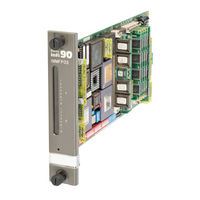
Multi-Function Processor Module
Brand: Bailey
|
Category: Controller
|
Size: 1 MB
Table of Contents
Advertisement