
Related Manuals for Delta Elektronika INT MOD SIM


Summary of Contents for Delta Elektronika INT MOD SIM
- Page 1 SM 3300 - Interfaces INT MOD SIM • INT MOD CON • INT MOD SER • INT MOD DIG • INT MOD ANA •...
- Page 3 SM 3300 - Interface modules General Features Models Description • Plug and play for the SM3300 series INT MOD SIM Simulation interface power supplies • INT MOD CON Isolated contacts interface Multiple interfaces possible per power supply • Isolated from the output voltage...
- Page 4 Pluggable, SM3300 interface slots 2, 3 or 4. Assembly See paragraph ‘Hardware Installation’ in this manual. Note 1: cannot be plugged in slot 1. Note 2: max 1pcs INT MOD SIM per unit. Note 3: cannot be combined with INT MOD ANA. Weight 70 g...
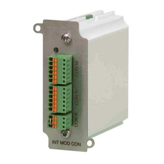
- Page 5 SM3300 INTERFACES DELTA ELEKTRONIKA BV Isolated Contacts Typical Applications • Trigger an external safety alarm • Interact in automated processes • Switch the output On/Off with a remote 24Vdc signal • Using a floating signal for triggering the Interlock function Specifications Relay contacts 1...
- Page 6 DELTA ELEKTRONIKA BV SM3300 INTERFACES Serial interface (multi-protocol) Typical Applications • RS232 Programming • Balanced RS422 Programming • USB Programming • Balanced RS485 Bi-directional Programming Specifications 2400, 4800, 9600, 19200, 38400, 57600, 115200 Communication speeds (bps) Insulation 1000 VDC Reinforced isolation acc. EN60950-1 / EN61010-1 prog.
- Page 7 SM3300 INTERFACES DELTA ELEKTRONIKA BV Digital User I/O Typical Applications • Hardware triggering of sequences • Interaction with other equipment • Stand-alone automation • Safety or Alarm indications Specifications Logic inputs 1... 8 2 - 30V Input range Rin = 22kOhm...
- Page 8 DELTA ELEKTRONIKA BV SM3300 INTERFACES Isolated Analog Controller interface Typical Applications • Analog programming of voltage and current • Analog monitoring of voltage and current • Remote monitoring of the status signals: OverTemp, Limit, PowerSink OverLoad • Remote Shut down of the power output using a 5V signal...
- Page 9 Failure to comply with the safety precautions or warnings in this document violates safety standards of design, manufacture and intended use of this equipment and may impair the built-in protections within. Delta Elektronika shall not be liable for user’s failure to comply with these requirements.
- Page 10 Unscrew the screws and remove the cover(s). • Always place the cover(s) back before connecting the unit to the mains supply again. 10 Environmental Conditions The Delta Elektronika power supplies safety approval applies to the following operating conditions: • Indoor use •...
- Page 11 Insert the interface and place the 2 screws back to secure the inter- • face. fig. 3 - 1 Positions for the INT MOD SIM. UNIT CONFIGURATION The unit will automatically detect the new inserted interface. • The interface icon will be shown in the display, see fig 3 - 2.
- Page 12 DELTA ELEKTRONIKA BV SM3300 INTERFACES fig. 3 - 3 PV Curve Name Description Unit Temperature at STC °C Irradiance at STC W/m² Maximum Power Point voltage mpp,stc Maximum Power Point current mpp,stc Open Circuit voltage oc,stc Short Circuit current sc,stc Temperature coefficient for the current, sometimes called alpha %/°C...
- Page 13 SM3300 INTERFACES DELTA ELEKTRONIKA BV 6.3 TABLE MODE The simulation interface also supports a table mode. With this table mode it is possible to simulate a custom curve. Or sim- • ulate a photovoltaic curve existing of multiple panels in series where some panels are shaded. In table mode the simula- tion module uses a table of 128 data points to program the current of the power supply.
- Page 14 DELTA ELEKTRONIKA BV SM3300 INTERFACES TABLE SIMULATION The simulation interface can simulate a custom curve based on a table as described in chapter . A separate application is • available specifically for this mode. With this application it is possible to manage, load and write tables from and to the simulation interface.
-
Page 15: Troubleshooting
SM3300 INTERFACES DELTA ELEKTRONIKA BV fig. 3 - 6 Foldback TROUBLE SHOOTING INTERFACE IS NOT DETECTED 11.1 Check the interface is in slot 2, 3 or 4, not in slot 1. • Check that there is only one simulation interface installed, and no analog interface. -
Page 16: Hardware Installation
SM3300 INTERFACES DELTA ELEKTRONIKA BV 4 ISOLATED CONTACTS Warning! carefully read the chapter "Safety Instructions" in this manual before connecting or operating the unit! CONDENSATION During normal operation, humidity will not harm the interfaces, • provided the air is not aggressive. The heat normally produced in the power supply will keep it dry. -
Page 17: Unit Configuration
4 -3 Ethernet commands. Refer to section 5.6 for the commands. Position of the interface icon in the unit display. Refer to the Delta Elektronika programming manual for Ethernet • (section 5.6) for commands. The manual is stored inside every SM3300 unit and can be downloaded via the web interface. -
Page 18: Serial Interface
SM3300 INTERFACES DELTA ELEKTRONIKA BV 5 SERIAL INTERFACE Warning! carefully read the chapter "Safety Instructions" in this manual before connecting or operating the unit! CONDENSATION During normal operation, humidity will not harm the interfaces, • provided the air is not aggressive. The heat normally produced in the power supply will keep it dry. -
Page 19: Serial Programming
DELTA ELEKTRONIKA BV SM3300 INTERFACES UNIT CONFIGURATION The unit will automatically detect the new inserted interface. • 0.0V 0.00A Menu The interface icon will be shown in the display, see fig 5 - 4. • For programming the voltage and/or current via the interface, set •... - Page 20 SM3300 INTERFACES DELTA ELEKTRONIKA BV Check that the power supply's output is not limited. • Consult the SM3300 manual about adjusting the limit settings. Check that both values for CV and CC are not zero. • It is not possible to program a voltage when the current control is set to zero and vice versa.
- Page 21 SM3300 INTERFACES DELTA ELEKTRONIKA BV 6 DIGITAL (USER) I/O Warning! carefully read the chapter "Safety Instructions" in this manual before connecting or operating the unit! CONDENSATION During normal operation, humidity will not harm the interfaces, • provided the air is not aggressive. The heat normally produced in the power supply will keep it dry.
-
Page 22: Inputs And Outputs
6 - 3 supply act like a Power PLC. Position of the interface icon in the unit display. Refer to the Delta Elektronika programming manual for Ethernet • (section 5.5) & Sequencer (section 6) for commands. The manual is stored inside every SM3300 unit and can be down- loaded via the web interface. - Page 23 SM3300 INTERFACES DELTA ELEKTRONIKA BV 7 ISOLATED ANALOG INTERFACE Warning! carefully read the chapter "Safety Instructions" in this manual before connecting or operating the unit! CONDENSATION During normal operation, humidity will not harm the interfaces, • provided the air is not aggressive. The heat normally produced in the power supply will keep it dry.
-
Page 24: Analog Programming
DELTA ELEKTRONIKA BV SM3300 INTERFACES UNIT CONFIGURATION The unit will automatically detect the new inserted interface. • 0.0V 0.00A Menu The interface icon will be shown in the display, see fig 7 - 3. • For programming the voltage and/or current via the interface, set •... - Page 25 SM3300 INTERFACES DELTA ELEKTRONIKA BV STATUS SIGNALS The status outputs have a separate Ø connection (pin 8) to avoid • unwanted offsets in the programming. 0.0V 0.00A Menu All the status outputs are logic outputs. Logic "0" means the out- •...
Need help?
Do you have a question about the INT MOD SIM and is the answer not in the manual?
Questions and answers