Advertisement
Available languages
Available languages
Quick Links
Advertisement

Related Manuals for Pando ORPAN E-251


Summary of Contents for Pando ORPAN E-251
- Page 1 CAMPANA E-251 GUIA INSTALACIÓN E-251 660066400106...
- Page 4 MANUAL DE INSTALACIÓN DE LA E-251 1º– MEDIDA MÍNIMA Para poder instalar la campana E-251 en nuestra cocina debemos tener presente que la distan- cia mínima entre el FORJADO y la parte vista del falso techo es de 210mm. Teniendo en cuenta que la distancia máxima de SUELO a FALSO TECHO no debe ser superior a 2,40 m.
- Page 5 MANUAL DE INSTALACIÓN DE LA E-251 3º– FIJACIONES A TECHO La campana E-251, se suministra con varillas roscadas, éstas se atornillan en el forjado. Enton- ces mediante unas tuercas se regula la campana a la altura deseada. (210mm a 370mm) Página 3...
- Page 6 MANUAL DE INSTALACIÓN DE LA E-251 4º– CONEXIÓNES Antes de proceder a cerrar el Falso Techo, debemos realizar las conexiones. Conexiones del tubo de salida de humos: la campana dispone de 2 salidas de Ø150 y 2 de 100x260 (Ø200) una en frontal y otra en el lateral. También dispone de salida por el techo de la cam- pana tanto en Ø150 ó...
- Page 7 MANUAL DE INSTALACIÓN DE LA E-251 5º– MEDIDAS AGUJEROS FALSO TECHO Cuándo se procede a cerrar el techo, a parte de hacerlo al nivel de la chapa inferior de la puer- ta, debemos tener la precaución de realizar el agujero adecuado para la correcta aspiración y funciona- miento de la campana.
- Page 8 MANUAL DE INSTALACIÓN DE LA E-251 CERRANDO CONTORNOS NOTA IMPORTANTE: Este modelo dispone de una iluminación de cortesía o luz ambiental que esta oculta en el peri- metral de los paneles de filtros. Es muy importante en el momento de cerrar el falso techo, no tapar las caras donde están situadas estas luces.
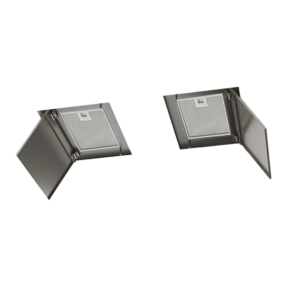
- Page 9 MANUAL DE INSTALACIÓN DE LA E-251 8º- PONER EN FUNCIONAMIENTO: Con las puertas abiertas y los filtros fuera, podemos ver la caja de conexiones, justo enfrente tenemos el interruptor de puesta en marcha de la campana. (si tenemos todas las conexiones realizadas con el motor exterior o de tejado) procedemos a ponerlo en marcha.
- Page 10 MANUAL DE INSTALACIÓN DE LA E-251 SINCRONIZACION CONTROL REMOTO (campanas de techo serie E) Tecla luz * Interruptor caja circuitos. ¡¡¡Importante!!! Una vez instalada la campana y conectado el interruptor de la caja de circuitos, antes de 20 segundos mantener pulsada la tecla luz del control remoto hasta que se enciendan las luces, de esta manera el circuito de la campana aprenderá...
- Page 11 MANUAL DE INSTALACIÓN DE LA E-251 DETALLES A TENER EN CUENTA: • Este modelo dispone de LUZ DE CORTESIA o LUZ AMBIENTAL. • A la hora de cerrar el falso techo, no se debe tapar la zona de la luz de cortesía. (Pág. 6) •...
- Page 12 MANUAL DE INSTALACIÓN DE LA E-251 No tapar el metacrilato Página 10 de luz de cortesía...
- Page 13 CONTROL REMOTO VERSIÓN CORIAN: (opcional sólo en determinados modelos, consultar distribuidor). 4 5 6 1. Encendido y apagado motor campana. 2. Disminuir velocidad motor. 3. Aumentar velocidad motor. 4. Temporizador motor, mantiene la campana encendida durante 10 minutos y luego se para. 5.
- Page 14 Pol. Ind. El Cros — Camí del Cros, S/N Apdo. Correos nº21 08310 ARGENTONA (Barcelona - Spain) The International Certification Network Quality Management System ISO 9001:2000 Tel. +34 93 757 94 11 Fax. +34 93 757 96 53 www.pando.es Página 12...
- Page 16 E-251 EXTRACTOR HOOD INSTALLATION GUIDE...
- Page 17 E-251 INSTALLATION MANUAL 1– MINIMUM DISTANCE Before the installation of the range hood E-251, you must ensure that there is a minimum dis- tance of 210 mm between the CEILING and the false ceiling. Please note that the maximum distance between the FALSE CEILING and the FLOOR should be no more than 2.40 m.
- Page 18 E-251 INSTALLATION MANUAL 3 - POSITIONING AND SECURING THE HOOD The E-251 range hood is supplied with threated rods which screw into the frame. The adjus- ting nuts can be used to set the required height for the range hood (between 210mm and 370mm). Page 3...
- Page 19 E-251 INSTALLATION MANUAL 4 – CONNNECTIONS All connections should be made before closing the FALSE CEILING. Fume extractor pipe connections: the hood has two Ø150 outlets and two 100x260 (Ø200) outlets, one on the front and other on the side. It also has a Ø150 or Ø200 outlet on the top of the ex- tractor hood for vertical pipe installations.
- Page 20 E-251 INSTALLATION MANUAL 5 - OUT CUT DIMENSIONS The FALSE CEILING should coincide with the lower level of the doors of the hood. For the correct operation of the hood and the effective aspiration, please pay attention to cut the holes follo- wing the exact measurements indicated on the drawing.
- Page 21 E-251 INSTALLATION MANUAL CLOSE THE OUTLINE IMPORTANT! The E-251 range hood has courtesy lighting, installed on the perimeter of the filters’ panels. Do not cover the lighting , when you install the false ceiling. 7 - PAINT THE DOORS OF THE HOOD Epoxy Finish allowing doors panels being painted same colour as ceiling.
- Page 22 E-251 INSTALLATION MANUAL 8 - COMISSIONING: Alter opening the doos and removing the filters, you can see the connection box. The ON switch for the extractor hood is opposite the connection box. If all the ceiling connections or exter- nal motor connections have been completed, you may start the extractor hood. ¡¡IMPORTANT !! After starting the hood, follow the instructions for to synchronize the RC (Page 8) Insert the filters and close the doors of the hood.
- Page 23 E-251 INSTALLATION MANUAL SYNCRONIZATION OF THE REMOTE CONTROL (ceiling hoods E-200/210 series) Light * switch/ diferencial case ¡¡¡Important!!! When the hood is installed and the differencial case is switched on, before 20 seconds pass, please keep pressed the button “light” until the lights of the hood swith on. This way the hood records the operating frequency of the remote control and toperating of the hood is correct.
- Page 24 E-251 INSTALLATION MANUAL POINTS TO BE CONSIDERED: This model has Internal LED courtesy lighting. Do not cover the lighting , when you install the false ceiling.(Page 6) Extraction conduit pipe connection to the extractor hood. Before the false ceiling is closed, some form of access panel must be installed on the side of the ext ractor hood where the conduit is connected The ceiling where the extractor hood is to be installed must be completely flat, with no uneeven areas of any kind.
- Page 25 E-251 INSTALLATION MANUAL Do not cover the the in- Page 10 ternal courtesy lighting...
- Page 26 E-251 INSTALLATION MANUAL Corian version remote control. User Instructions. 4 5 6 1. Hood motor on and off. 2. Reduce motor speed. 3. Increase motor speed. 4. Motor timer, keeps the hood on for 10 minutes and then switches it off. 5.
- Page 28 HOTTE E-251 GUIDE D’INSTALLATION E-251 660066400106...
- Page 29 1er—DIMENSIONS MINIMALES Pour pouvoir installer la hotte E-251 dans votre cuisine, vérifiez que la distance minimale entre le PLAFOND et le faux plafond est bien de 210mm. Veuillez noter que la distance maximale entre le SOL et le FAUX PLAFOND ne dépasse pas les 2,40 m. Les tiges filetées fournies avec la hotte permettent de régler la hauteur de 210 a 370 mm.
- Page 30 3ème– FIXATION AU PLAFOND Vissez les tiges filetées (fournies avec la hotte) au plafond. On peut régler la hauteur de la hot- te (de 210 à 370 mm) à l’aide des écrous. Page 3...
- Page 31 4ème– CONNEXIONS Réalisez les connexions avant de fermer le faux plafond. Connexions de tuyau d’évacuation des fumées: la hotte dispose de 2 sorties de Ø150; et de 2 sorties de 100x260 (Ø200) , une sur la partie avant et l’autre sur la partie latérale. La hotte dispose aussi de la sortie d’évacuation par le toit de Ø150 ó...
- Page 32 5ème– MESURES DE TROU DANS LE FAUX PLAFOND Pour assurer bon fonctionnement et aspiration de la hotte , il faut réaliser les trous appropiés aux mesures de la hotte. Réalisez dans le faux plafond les 2 trous de 710x460mm avec la distance de 306mm entre eux.
- Page 33 Fermez le contour des trous IMPORTANT!!!: Ce modèle a l’éclairage d’ambiance, qui est caché dans le périmètre des panneaux des filtres. Au moment de fermer le faux plafond, il est très important de ne pas couvrir les superficies d’éclairage d’ambiance. 7 ème –...
- Page 34 8ème — MISE EN MARCHE: Avec les portes ouvertes et les filtres retirés, vous pouvez voir le boîtier de connexions; l’interrupteur de mise en marche de la hotte se trouve juste en face. (si vous avez effectué toutes les connexions), vous pouvez mettre en marche la hotte. IMPORTANT!! Après avoir effectué...
- Page 35 MANUEL D’INSTALLATION DE LA HOTTE E-220 SYNCHRONISATION DE TÉLÉCOMMANDE (hottes plafonnières / serie E) Lumière Interrupteur/ boîte des circuits. ¡¡¡Important!!! Après avoir installé la hotte et connecté l’interrupteur de la boîte des circuits de la hot- te, avant de que passent 20 secondes, appuyez la touche de “lumière” et gardez-la en- foncée, jusqu’à...
- Page 36 DÉTAILS À PRENDRE EN COMPTE: Ce modèle a L’ÉCLAIRAGE D’AMBIANCE.. • Au moment de fermer le faux plafond, il est important de ne pas couvrir la zone d’éclairage • d’ambiance (Page 6). Connexion à la hotte de tube conduit d’évacuation. •...
- Page 37 Ne pas fermez le méthacrylate Page 10 d’éclairage d’ambiance.
- Page 38 Telecommande version corian . Instructions. 1. Mise en marche et arrêt moteur hotte. 2. Diminuer vitesse moteur. 3. Augmenter vitesse moteur. 4. Temporisateur moteur, permet de maintenir la hotte allumée pendant 10 minutes pour s'éteindre ensuite. 5. Led indicatrice de pression de la touche télécommande. Indique aussi le processus de programmation. 6.
- Page 39 ANNNEXE (DIMENSIONS MOTEURS EXTÉRIEURS)
- Page 40 Pol. Ind. El Cros — Camí del Cros, S/N Apdo. Correos nº21 08310 ARGENTONA (Barcelona - Spain) The International Certification Network Quality Management System ISO 9001:2000 Tel. +34 93 757 94 11 Fax. +34 93 757 96 53 www.pando.es Página 12...
Need help?
Do you have a question about the ORPAN E-251 and is the answer not in the manual?
Questions and answers