
Related Manuals for Optoelectronics Spectrum Scout


Summary of Contents for Optoelectronics Spectrum Scout
- Page 1 OPTOELECTRONICS ® 160 West Camino Real #233 Boca Raton, FL 33432 Telephone: 954-642-8997 Fax: 954636-3533 sales@optoelectronics.com www.optoelectronics.com Copyright 2008©...
- Page 2 Spectrum Scout USER MANUAL...
-
Page 3: Table Of Contents
Table of Contents Introduction Front Panel Top Panel Getting Started Function Button Reaction Tune 9-10 Memory Download and Datalogging Upload a Database Specifications What to Expect Antennas and Accessory Recommendations Factory Service/Warranty Optoelectronics, ICOM, AOR, Microsoft are registered trademarks. - Page 4 Warranty PRODUCT WARRANTY Optoelectronics, Inc. warrants all products and accessories for one (1) year against defects in materi- als and workmanship to the original purchaser. Products returned for warranty service will be repaired or replaced at Optoelectronics’ option. Specifically excluded are any products returned under this warranty that upon examination, have...
- Page 5 30dB of attenuation. SERIAL DATA INTERFACE The Spectrum Scout incorporates an RS232 interface for the purpose of interfacing to a PC. The fre- quencies saved to memory may be downloaded using the Spectrum Scout download program. The Spectrum Scout may also log frequencies to the PC in real time using the Spectrum Scout datalogging program.
- Page 6 WARNING - Maximum antenna input signal is +15dBm (50mW). Under no circumstances should the Spectrum Scout be directly connected to an RF transmitter or be used in close proxim- ity to a radio transmitter of more than 5 watts. Damage to the input amplifier circuitry is readily apparent and will not be covered under warranty.
-
Page 7: Introduction
5, and 10MHz. This allows for easy lookup of the FCC bandplan information. A great feature of the Spectrum Scout is its ability to allow the user to upload their own frequencies for their specific location. Using simple text files and and an upload program that is supplied by Optoelectronics, you can easily load your own information for specific frequencies. - Page 8 30dB of attenuation in the FM band. Knocking down the background RF by 30dB will allow the Spectrum Scout to see that 15dB signal from a greater distance. This is not to say it will not work in high RF areas, however it is something that should be taken into account.
- Page 9 Specifications Input Impedance: 50 Ohm Frequency Range: 10MHz - 2.6GHz Sensitivity: <3mV Maximum Input: +15dBM, 50 milliwatts Resolution: 1kHz / 250.000 or 100Hz / 250.0000 Display: 2x16 alphanumeric LCD with EL Backlight Timebase: 10MHz Size: 3.5”H x 3”W x 1.5”D Weight: 12 oz Battery:...
-
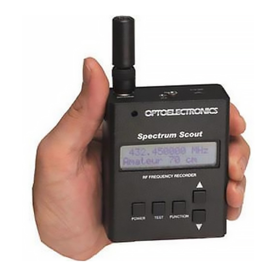
Page 10: Front Panel
Front Panel TEST FUNCTION POWER POWER: Press and hold for 3 seconds to turn the unit ON. Once on, press and hold the button for two seconds to turn the backlight ON. Press and hold the button for 4 seconds to turn the unit OFF. TEST: Press the button when you wish to return to the frequency display when in any other mode. -
Page 11: Top Panel
CALIBRATION: The calibration adjustment hole is located to the left of the Optoelectronics logo on the front panel. The calibration is set at the fac- tory and should not be altered. Altering the adjustment can result in inaccurate frequency measurements. - Page 12 420.0000,450.0000,Amateur 70 cm 147.1000,147.1000,Club Repeater 2 To upload a database please visit our web site and enter the Spectrum Scout page. There you will find the upload program and instructions on how to make a database and upload that database.
- Page 13 Memory saved to the Spectrum Scout may be downloaded to a computer through the RS232 interface jack located on top of the Spectrum Scout. All 1000 memories and 65,000 hits may be downloaded and saved for later use. Real time datalogging is also possible through the RS232 jack. The connection to the PC is direct using the Spectrum Scout serial cable (CBDS sold separately).
-
Page 14: Getting Started
If the backlight is on press and hold the POWER button for 2 seconds to turn it off. Display Options When powered on the Spectrum Scout defaults to signal strength mode. The unit can display either signal strength or FCC bandplan data. Press and hold the FUNCTION button and then press either the UP/DOWN arrow buttons to switch between the two. -
Page 15: Function Button
UP/DOWN arrow button to switch from AUTO STORE Disabled to Enabled. If Auto Store is disabled you may also manually store a frequency to memory by pressing and holding the TEST button for two seconds. This will store what is being displayed on the Spectrum Scout at that moment. -
Page 16: Reaction Tune
C. PCR1000: The Spectrum Scout can Reaction Tune the ICOM PCR1000. The CBPCR Reaction Tune cable is required and it interfaces through the RS232 jack on top of the Spectrum Scout. The PCR1000 part of the cable plugs into the DB9 connector on the back of the receiver. Since the PCR1000 has no hardware volume or squelch controls the Spectrum Scout is capable of controlling these functions as well. - Page 17 Reaction Tune When the Spectrum Scout is in FILTER mode it can Reaction Tune a receiver connected through the CI5 port on the top panel. Following are the procedures for Reaction Tuning the various receivers that are compatible with the Spectrum Scout.
- Page 18 Function Button Frequency Database You may scroll through the entire database to use as a reference tool by using the UP/DOWN arrow button for FINE tune. You may also scroll by pressing and holding the FUNCTION button and press- ing the UP/DOWN arrow button for COARSE tune. See next step for adjusting step sizes. Coarse Step There are 3 different settings for COARSE tune, 1, 5 and 10 MHz .
- Page 19 Reaction Tune is used when interfacing to compatible receivers. Receiver Type CI5 for ICOM, and Optoelectronics receivers, AR8000 for AOR receivers and PCR1000. PCR1000 Volume When interfaced to an ICOM PCR1000 in Reaction Tune mode you may control the volume of the receiver by pressing the UP/DOWN arrow buttons.
- Page 20 Note: If you disable the default database and the other two available databases have no data, or are not enabled if they do have data, then the Spectrum Scout will not display any FCC bandplan data when the unit locks on a signal.
Need help?
Do you have a question about the Spectrum Scout and is the answer not in the manual?
Questions and answers