Table of Contents
Advertisement
Quick Links
Advertisement
Table of Contents

Related Manuals for Optoelectronics M1


Summary of Contents for Optoelectronics M1
- Page 1 © Copyright 2016 Optoelectronics, Inc. U.S. Patents 5,471,402 & 5,710,710 OPTOELECTRONICS ® 160 West Camino Real #233 Boca Raton, FL 33432 Telephone: 954-642-8997 Fax: 954-636-3533 Email: sales@optoelectronics.com Internet: www.optoelectronics.com...
- Page 2 USER MANUAL...
-
Page 3: Table Of Contents
Table of Contents Introduction Controls Operation Operating Modes Operational Characteristics Signal Strength Bargraph Display Resolution Specifications 13 - 14 Antenna and Accessory Recommendations Factory Service 16-17... - Page 4 WARNING - Maximum antenna input signal is +15dBm (50mW). Under no circumstances should the M1 be directly connected to an RF transmitter or be used in close proximity to a radio transmitter of more than 5 watts. Damage to the input amplifier circuitry is readily appar- ent and will not be covered under warranty.
-
Page 5: Introduction
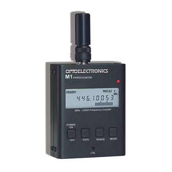
RF. The M1 is more than a test instrument in the traditional sense because it is useful for finding frequencies being used for two way radio communications. Designed to work with an antenna to pick up transmitted radio frequencies, it is actually a frequency recorder. -
Page 6: Controls
The 2.8GHz (Prescale) range completely covers all VHF and UHF communications so it is fine to leave the M1 in this range all the time. The advantage of the direct 250MHz range is that it is much faster to respond and it gives a measurement with more digits of resolution. If you are frequency finding and do not know the range to look it is best to use the 2.8GHz range. - Page 7 Pressing the MODE button again will activate Recall mode. Recall mode is indicated by “Recall” being displayed on the top row of the LCD. CI-5 The jack labeled CI-5 on top of the M1 is used for interfacing to the Optoelectronics Optolinx for the purpose of computer controlled operation or datalogging. 9-12VDC The connector labeled 9-12VDC on top of the M1 is used for accepting the plug from the supplied AC90 power adapter.
-
Page 8: Operation
Immediate response to frequencies that are 10 to 15 dB greater the the background RF floor is possible. This is simply done by moving the M1 in the nearfield of the transmitter. The nearfield is the area close to the antenna where the field strength is high but falling off rapidly as distance increases. -
Page 9: Operating Modes
The corresponding memory location will be displayed to the left of the frequency starting at 00 and ending at 99. The M1 will only log a unique frequency to a mem- ory location. If the M1 captures the same frequency repeatedly it will not write those frequencies to... - Page 10 Operating Modes (cont.) Recall Mode To enter recall mode press the MODE button until “Recall” is displayed on the LCD. The first memo- ry location, (00), will be displayed along with the frequency logged to that memory. To scroll forward through the frequencies in memory press the RANGE button.
-
Page 11: Operational Characteristics
Strong Signal Overload The M1 can be overloaded in the presence of a strong RF signal. In this situation the bargraph will also display a strong signal indication. It may be necessary to reduce the signal level by moving away from the transmitter or removing/shortening the antenna before the counter begins to count properly. -
Page 12: Signal Strength Bargraph
RF energy detected by the M1 at that instant. It is important to note that the RF signal strength bargraph always provides a real-time signal level indication, whereas the fre- quency display may show a frequency which was detected at some time in the past. -
Page 13: Display Resolution
Display Resolution Frequency Display Resolution Least significant digit displayed (LSD) as a function of Gate Time and Range Range Gate Time Meas. Time Sample Display 250MHz 100us 13mS 10kHz 150.00 13mS 1kHz 150.000 10mS 13mS 100kHz 150.0000 100mS 110mS 10Hz 150.00000 150.000000 0.1Hz... -
Page 14: Specifications
Specifications The M1 has the maximum amount of broad gain possible without driving the front end circuitry into hard self oscillation. The purpose of this concept is to permit the maximum possible pick-up distance from radio transmitters. There is no gain or sensitivity adjustment possible in the circuit. Specific sensitivities at par- ticular frequencies are difficult to predict with precision in production units. - Page 15 Specifications (cont.) Time Between Measurements: 10 milliseconds, all range & gate times Display: 10 digit LCD. Decimal at MHz point Timebase: 10MHz setable to +/- 1ppm (Option 1ppm TCXO) RF Signal Strength Bargraph: 16 segments, approximately 3dB segments, Relative indication only Size: 3.7”...
-
Page 16: Antenna And Accessory Recommendations
M1. The Optolinx comes supplied with the CB-CI5 cable, which is necessary in order to inter- face the M1 to the Optolinx for downloading. -
Page 17: Factory Service
Factory Service PRODUCT WARRANTY Optoelectronics, Inc. warrants all products and accessories for one (1) year against defects in materi- als and workmanship to the original purchaser. Products returned for warranty service will be repaired or replaced at Optoelectronics’ option. Specifically excluded are any products returned under this warranty that upon examination, have... - Page 18 Factory Service RETURN POLICY The Optoelectronics Service Department will provide rapid turnaround of your repair. A return authorization is required. Enclose complete information as follows: 1. Copy of sales receipt if under warranty. 2. Detailed description of problem(s). 3. Complete return address and phone number (UPS street address for USA).
Need help?
Do you have a question about the M1 and is the answer not in the manual?
Questions and answers