Table of Contents
Advertisement
Available languages
Available languages
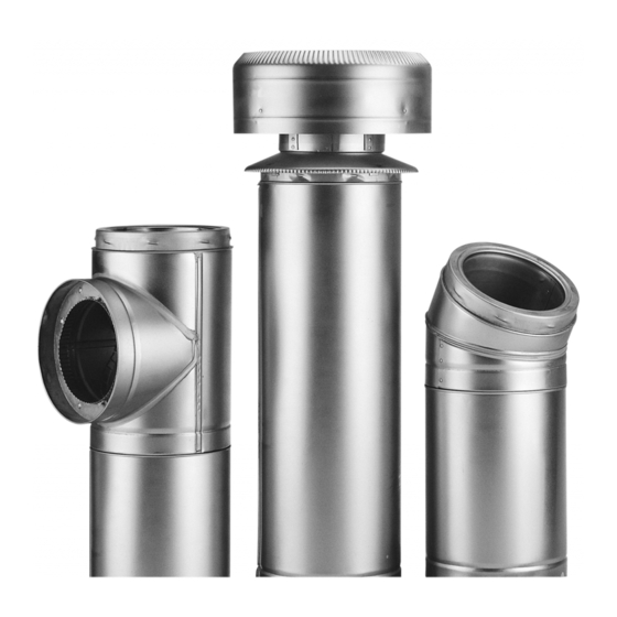
SUPERVENT (SC & FC)
SUPERPRO (SPR)
FACTORY BUILT
INSULATED CHIMNEY
LISTED
SELKIRK CORPORATION
5030 Corporate Exchange Blvd. SE,
Grand Rapids, MI 49512
1.800.992.VENT (8368)
©2021 SuperVent / SuperPro
&
Tested to
UL 103 Type HT
and
CAN/ULC-S604
All Rights Reserved
A MAJOR CAUSE OF VENT
RELATED FIRES IS FAILURE TO
MAINTAIN REQUIRED
CLEARANCES (AIR SPACES) TO
COMBUSTIBLE MATERIALS.
IT IS OF THE UTMOST
IMPORTANCE THAT THIS
CHIMNEY SYSTEM BE
INSTALLED ONLY IN
ACCORDANCE WITH THESE
PLEASE READ ALL INSTRUCTIONS
BEFORE BEGINNING YOUR
FAILURE TO INSTALL THIS SYSTEM IN
ACCORDANCE WITH THESE
INSTRUCTIONS WILL VOID THE
CONDITIONS OF CERTIFICATION AND
THE MANUFACTURER'S WARRANTY.
Installer: It is of the utmost importance that
these instructions are left with the homeowner.
Homeowner: Keep these instructions and
maintenance guide in a safe place for future
1
I
NSTALLATION
M
AINTENANCE
(C
& U
ANADA
INSTRUCTIONS.
INSTALLATION.
reference.
SELKIRK CANADA CORPORATION
950 South Service Road, Second Floor
3010122
I
NSTRUCTIONS
&
G
UIDE
S
)
NITED
TATES
Stoney Creek, ON L8E 6A5
1.888.SELKIRK(735.5475)
02/12/2021
Advertisement
Chapters
Table of Contents

Subscribe to Our Youtube Channel
Related Manuals for Selkirk SUPERVENT SC


Summary of Contents for Selkirk SUPERVENT SC
- Page 1 Homeowner: Keep these instructions and maintenance guide in a safe place for future CAN/ULC-S604 LISTED reference. SELKIRK CORPORATION SELKIRK CANADA CORPORATION 5030 Corporate Exchange Blvd. SE, 950 South Service Road, Second Floor Grand Rapids, MI 49512 Stoney Creek, ON L8E 6A5 1.800.992.VENT (8368) 1.888.SELKIRK(735.5475)
-
Page 2: Table Of Contents
TABLE OF CONTENTS CERTIFICATION LABELS TYPE OF APPLIANCES PRE INSTALLATION GUIDELINES 4, 5 TOOLS FRAMING DETAILS CEILING SUPPORT INSTALLATION 5, 6 STOVE PIPE ADAPTOR ADJUSTABLE LENGTH 6, 7 ATTIC INSULATION SHIELD INSTALLATION 7, 8 FIRESTOP RADIATION SHIELD INSTALLATION 8, 9 ELBOW INSTALLATION WALL SUPPORT INSTALLATION (AWS) 9, 10, 11... -
Page 3: Certification Labels
CERTIFICATION LABELS SELKIRK CANADA CORPORATION 09/29/20 SELKIRK CANADA CORPORATION 09/29/20... -
Page 4: Type Of Appliances
TYPE OF APPLIANCES mounted on 2” x 4” studs is typically used in this situation. The space between the outer wall of the chimney and the enclosure must be a least a minimum of 2 inches. U.S.A. APPLICATIONS In the U.S.A., Model SuperVent/SuperPro has been tested per UL103 The National Fire Protection Association Standard 211 states: Factory- as a "Type HT"... -
Page 5: Tools
365 x 365 305 x 305 Do not mix and match with other manufacturer's products. Use only 13 x 13 x 13 x 14 Selkirk's Models JSC/SPR/JFC listed components. (175mm) 330 x 330 340 x 340 365 x 365 14 x 14... -
Page 6: Stove Pipe Adaptor
The exception to this is a double wall Support Installation. Frame (on all 4 sides) a level square opening to stove pipe, such as Selkirk's Model DSP which can be installed the dimensions specified in the Framing Dimension Table 1. -
Page 7: Attic Insulation Shield Installation
5. Remove insulation from the inlet (female) end of the Adjustable FIRESTOPPING Length until the insulation is level with the line marked on the outside Firestopping is required at every joist level. Wherever a chimney of the pipe (See Fig. 7). passes through a ceiling or floor, through a wall, or into an enclosure, 6. - Page 8 FRAMING DIMENSION CHART Table 2 FOR ATTIC INSULATION SHIELD DIAMETER 6” 7” 8” 5” OF CHIMNEY FRAMED 12 x 12 13 x 13 14 x 14 11 x 11 OPENING 7 -1/4” 8 -1/4” 10 -1/4” 9 -1/4” “A” DIM. 11”...
-
Page 9: Elbow Installation
Rain Cap Rain Cap FIGURE 13 FIGURE 14 Storm Collar Storm Collar Ventilated Flashing Ventilated Flashing Roof Joist Roof Joist (Framed all 4 sides) (Framed all 4 sides) Chimney Sections Attic Space Attic Space Attic Insulation Shield (AIS) Attic Insulation Shield Ceiling Joist Floor, Ceiling Joist (Framed all 4 sides) -
Page 10: Wall Support Installation (Aws)
For a non combustible wall, cut a hole 3/16" greater than the outside Rain Cap diameter of the chimney. FIGURE 15 NOTE: To reduce cold air infiltration into the dwelling you can install the optional Universal Shielding Insulation (JUSI) Storm Collar into the Wall Thimble. - Page 11 ADJUSTABLE INTERMEDIATE Use a non-hardening high-temperature silicone sealant (500°F) to seal around the horizontal chimney length where it enters through the WALL SUPPORT (AIWS) exterior of the Wall Thimble or the concrete wall. If the total chimney height exceeds the Wall Support (AWS) limitations an Adjustable Intermediate Wall Support must be installed.
- Page 12 outline of the hole and drill a pilot hole in its center. - Break out part of the wall covering within the outline to confirm that the hole will be centered between studs and that no electrical wires Distance Table 4 - Wall Support Chimney Height Chart could be cut by the saw.
- Page 13 5. Assemble the 2 side Brackets (point of triangle facing down) to 7. From outside the building, slide the assembly (Chimney Length the Support Plate (flange up and threaded stud towards the wall) by installed on the Tee Branch) through the Wall Thimble ensuring the male inserting the threaded studs into the oblong slots (see Figures 22 &...
- Page 14 Support Brackets using (8) #14 x 1-1/2" hex head lag screws or #10 13. From inside the building, for an extension of the Insulated Tee, x 2" wood screws. Make sure they go into solid bracing as per the slide an appropriate Insulated Chimney Length through the Wall requirements in Table 3 Section B and Figure 21(B), below the Thimble to the horizontal branch of the Insulated Tee.
- Page 15 NOTE: If ground clearance does not permit the installation of the Wall 21. Place the two halves of the UWB Band as shown in Figure 21. Insert the flat head bolt through the middle set of holes in the band Support with the Support Bracket facing down, it is permissible to halves marked with the corresponding pipe diameter of the chimney invert these brackets, if in a non-combustible wall application.
-
Page 16: Cathedral Ceiling Support Installation
27. Level the brackets and drill pilot holes in the wall using the 1. After framing in your opening to the dimensions specified in Table mounting holes in the brackets as a template. Drill 1 hole in the wall 1 found in the Framing Details section (measured in the horizontal for each bracket. -
Page 17: Rafter Radiation Shield Installation
its feet (support bracket) resting over rafters or a framed opening to 6. Chimney sections (15 ft max.) installed below the Cathedral Ceiling form a solid base. Frame a rectangular roof opening to provide a 2" Support are locked together from below by turning clockwise until minimum air space clearance from combustible materials. -
Page 18: Roof Flashing Installation
Slide the top edge (nearest the roof peak) of the Flashing under the NOTE: A Rubber Boot Flashing Kit (URBFK) is available as an option roof shingles. At least half of the Flashing should be UNDER the for passing through a corrugated or metal roof. See separate instruc- shingles and the bottom edge OVER the shingles to provide a tions packaged with the Rubber Boot Flashing Kit. - Page 19 F. Assemble the telescoping legs by sliding the supplied hose clamp over larger diameter leg and then inserting smaller diameter leg into larger diameter leg. Temporarily hold legs together by tightening the hose clamp over the cut section of larger diameter leg (see Figure 32). Repeat for the other telescoping leg assembly.
- Page 20 J. Make sure the chimney is level and plumb. Check all required dimensions and angles, adjust if necessary. For added security, lock legs in place by Smaller Diameter Leg using 1/8” x 1/2” stainless steel self tapping screw (supplied) through 2”...
-
Page 21: Maintenance And Cleaning Of Chimney
sealed if necessary to prevent the constant flow of air through the MAINTENANCE AND CLEANING OF CHIMNEY: system. “Creosote and Soot - Formation and Need for Contact a professional certified chimney sweep for chimney cleaning Removal” services and advice if you have any doubts about your ability to clean your chimney system or if the task is too large. -
Page 22: Chart 1 - Offset Chimney Installation
CHART 1 - OFFSET CHIMNEY INSTALLATION It may be necessary to offset the chimney in order to clear a joist or an obstacle. The three (3) charts below will assist you in selecting the proper combination of elbow angle and chimney length(s) that will provide the necessary degree of offset within an available height. OFFSET CHART 1. -
Page 23: Chart 2 - Chimney Height Above The Roof
CHART 3 - Connector Pipe Clearance below Cathedral Support 1. Identify the type of connector pipe you will be installing, single wall (requires 18" clearance to combustibles) or Selkirk's Double Wall Stove Pipe (model DSP) which requires 6" clearance to combustibles. -
Page 24: Replacement Parts List
REPLACEMENT PARTS LIST SUPERPRO SUPERVENT DESCRIPTION PART N PART N 48" Chimney Length SPR*L48 36" Chimney Length SPR*L36 JSC*SA3 24" Chimney Length SPR*L24 JSC*SA2 18" Chimney Length SPR*L18 JSC*SA18 12" Chimney Length SPR*L12 JSC*SA1 6" Chimney Length SPR*L6 JSC*SA6 SPR*AL JSC*AL 12"... - Page 25 INSTALLATION INFORMATION Leave with homeowner. Homeowner: Keep in a safe place for future reference. PRODUCT INFO SuperVent / SuperPro CHIMNEY MODEL : FLUE SIZE________ TOTAL HEIGHT_________ INSIDE INSTALLATION OUTSIDE INSTALLATION CONNECTED TO (type of appliance): BOILER FURNACE LISTED FACTORY-BUILT FIREPLACE OTHER (specify) ____________________ LOCATION OF APPLIANCE: BASEMENT...
- Page 26 Propriétaire: Gardez les directives d’installation et guide d’entretien dans un endroit sécuritaire CAN/ULC-S604 LISTÉE pour référence future. SELKIRK CORPORATION SELKIRK CANADA CORPORATION 5030 Corporate Exchange Blvd. SE, 950 South Service Road, Second Floor Grand Rapids, MI 49512 Stoney Creek, ON L8E 6A5 1.800.992.VENT (8368) 1.888.SELKIRK(735.5475)
- Page 27 ÉTIQUETTES DE CERTIFICATION TYPES D’APPAREILS 4, 5 DIRECTIVES AVANT L’INSTALLATION OUTILS DÉTAILS DE LA STRUCTURE 5, 6 INSTALLATION DU SUPPORT DE PLAFOND DÉCORATIF INSTALLATION DU TUYAU DE POÊLE 6, 7 LONGUEUR AJUSTABLE 7, 8 INSTALLATION DE L'ÉCRAN THERMIQUE DE GRENIER 8, 9 INSTALLATION DU COUPE-FEU DE SOLIVE INSTALLATION DU COUDE...
-
Page 28: Étiquettes De Certification
ÉTIQUETTES DE CERTIFICATION SELKIRK CANADA CORPORATION 09/29/20 SELKIRK CANADA CORPORATION 09/29/20... -
Page 29: Types D'appareils
matériaux combustibles doit être entourée d'un enclos afin de TYPES D'APPAREILS prévenir tout dommage et contact corporel. L’enclos peut être fabriqué en utilisant des matériaux de construction réguliers, APPLICATIONS AU ÉTATS-UNIS souvent du gyroc monté sur des goujons de 2 po. x 4 po. est utilisés Au États-Unis le modèle SuperVent/SuperPro est une cheminée dans cette situation. -
Page 30: Outils
365 x 365 Utilisez uniquement les composants répertoriés dans les modèles 14 x 14 x 14 x 14 JSC/SPR/JFC de Selkirk. (200mm) 365 x 365 365 x 365 355 x 355 N.B.: *Quand vous coupez la surface "finie" à l'intérieur de votre mur ou DIMENSION DE LA CHEMINÉE... -
Page 31: Installation Du Tuyau De Poêle
à ceci, il s'agit du tuyau de poêle à parois double, modèle l'ensemble dans l’ouverture prévue en procédant par en-dessous. Assurez- "DSP" de Selkirk. Il peut être installé à des dégagements réduits de vous que la plaque de finition soit égale au plafond et que le montage soit de 6 pouces aux combustibles. -
Page 32: Installation De L'écran Thermique De Grenier
PROTECTION CONTRE LE FEU 5. Enlevez l’isolation du bout femelle de la longueur réglable jusqu’à ce que l’isolation soit de niveau avec la ligne marquée sur l’extérieur Une protection contre le feu est requise à chaque solive de plancher de la longueur (schéma 7). ou plafond, là... -
Page 33: Installation Du Coupe-Feu De Solive
TABLEAU D'ENCADREMENT POUR LE Tableau 2 PARE-FEU POUR LE GRENIER DIAMÈTRE DE 6” 7” 8” 5” CHEMINÉE OUVERTURE 12 x 12 13 x 13 14 x 14 11 x 11 ENCADRÉE 7 -1/4” 8 -1/4” 10 -1/4” 9 -1/4” “A” DIM. 11”... -
Page 34: Installation Du Coude
Chapeau de cheminée Chapeau de cheminée SCHÉMA 13 SCHÉMA 14 Collet de solin Collet de solin Solin ventilé Solin ventilé Solive de toit Solive du toit (Encadrez 4 côtés) (Encadrez 4 côtés) Sections de cheminée Grenier Grenier Écran thermique pour grenier Écran thermique pour grenier (AIS) Solive de plafond... -
Page 35: Installation Du Support Mural (Aws)
Pour les murs de béton, coupez un orifice légèrement plus grand (3/16po) Chapeau de que la cheminée. cheminée SCHÉMA 15 N.B.: Pour réduire l'infiltraion d'air froid dans le logement, Collet de solin vous pouvez installer avec le support de plafond cathédral l'isolant universel (JUSI) pour les coupe-feux (facultatif). -
Page 36: Installation Support Mural Intermédiaire (Aiws)
SUPPORT MURAL INTERMÉDIAIRE - AIWS Employez un calfeutrant à la silicone à hautes températures (500°F) non durcissant pour scellerr autour de la longueur de cheminée horizontale Si la hauteur totale de la cheminée excède les limites du support mural, là où elle traverse l'extérieur de la bague murale ou un mur en béton. un support mural intermédiare ajustable doit être installé... - Page 37 Employez un trouveur de goujon pour localiser les goujons de murs. Marquez le contour du trou et forez un trou pilote à son centre. Créer une petite ouverture pour confirmer que le trou sera centré entre les goujons et q’aucuns fils électriques seront coupés par la Tableau 4 - Hauteur de cheminée au-dessus du support Distance du scie.
- Page 38 7. À partir de l’extérieur de l’immeuble, glissez la longueur de cheminée Assemblez les 2 crochets (pointe du triangle vers le bas) à la (installée précédemment au branchement du té) dans la bague murale plaque de support (collet vers le haut et tige filetée vers le mur) en en vous assurant que l’accouplement male du té...
- Page 39 #10 x 2". Assurez-vous que les boulons de coffrage passeront dans Pour une rallonge au té, installez une longueur de cheminée isolée les goujons du mur selon les conditions trouver à la section B au de 12 pouces (ou davantage si requis - ne pas dépasser 24 pouces) tableau 3 et au schéma 21 (B) au-dessous de l’ouverture préparée pour au branchement horizontal du té...
-
Page 40: Brides Murale
Placez les deux moitiés de la bride UWB suivant les indications N.B. : Si le dégagement au sol ne permet pas l’installation du support du schéma 30. Passez le boulon supporteur principal dans un des mural avec les crochets de support vers le bas, il est permis d’inverser ces crochets, si l'installation est pour un mur non-combustible. -
Page 41: Installation Du Support De Plafond Cathédral
1. Après avoir structuré votre ouverture aux dimensions spécifiées Vérifier les dégagements et le plomb de la bride. Percer des trous au tableau 1, glissez le support cathédral dans l'ouverture de la solive. pilotes dans le mur en vous servant des crochets comme gabarit. Fixez les crochets au mur en utilisant 2 boulons de coffrage de 2. -
Page 42: Installation Du Coupe-Feu Radiant
6. Les sections de cheminée (15 pieds de maximum) installées sous le se reposent sur le toit au-dessus des chevrons ou d’une ouverture support de plafond cathédral sont bloquées en place en les tournant encadrée pour une base solide. Préparez une ouverture rectangulaire dans le sens horaire jusqu’à... -
Page 43: Installation De L'hauban De Toit
Glissez la partie supérieure (le plus près du pignon) du solin sous les N. B. : Un ensemble de solin en caoutchouc (URBFK) est offert en option bardeaux de toiture. Au moins la moitié du solin devrait être SOUS les pour passer une cheminée à... - Page 44 F. Assemblez les jambes télescopiques en glissant la pince de serrage sur la jambe à diamètre supérieure et insérée la jambe à diamétre inférieure dans celle-ci. Retenez temporairement les jambes ensemble en serrant la pince de serrage sur la section coupée de la jambe à diamètre supérieure (schéma 32).
-
Page 45: Entretien Et Nettoyage De La Cheminée
J. Assurez-vous que la cheminée est de niveau et d’aplomb. Vérifiez toutes dimensions et angles exigés, ajustez si nécessaire. Pour sécurité Jambe télescopique de additionnelle, bloquer en place les jambes télescopiques en utilisant des petit diamètre Écrous de 2po vis en acier inoxydable 1/8” x 1/2” (fourni) en utilisant les trous pilotes trouvés à... -
Page 46: Charte 1 - Tableau De Décalage
Si vous avez des doutes à votre capacité de nettoyer la cheminée ou Entretien et nettoyage de la cheminée que la tâche est trop grande, nous recommandons fortement de contacter un ramoneur certifié pour obtenir ses services pour le “Créosote et suie - Formation et nécessité de nettoyage de la cheminée et pour prendre ses conseils. -
Page 47: Charte 2 - Hauteur De Cheminée Requis
CHARTE 1 - DÉCALAGE POUR CHEMINÉE Le besoin d'utiliser un ensemble de coude devient nécessaire pour dévier la cheminée afin de degager un obstacle ou un colombage. Les trois tableaux ci-dessous vous aideront à sélectionner la combinaison de coude et de longueurs nécessaires pour obtenir le degré d’angle nécessaire dans une hauteur disponible. -
Page 48: Liste Des Pièces De Rechange
CHARTE 3 - Dégagement au tuyau de poêle en-dessous du support cathédral 1. Identifiez le type du tuyau de raccordement que vous allez utiliser: paroi simple (1) ou le modèle DSP tuyau de poêle à double paroi de Selkirk (2). -
Page 49: Dosier Du Produit
LISTE DES PIÈCES DE RECHANGE SUPERPRO SUPERVENT DESCRIPTION . de pièce . de pièce Longueur de 48 po. SPR*L48 SPR*L36 JSC*SA3 Longueur de 36 po. SPR*L24 JSC*SA2 Longueur de 24 po. Longueur de 18 po. SPR*L18 JSC*SA18 Longueur de 12 po. SPR*L12 JSC*SA1 Longueur de 6 po. - Page 50 INFORMATION DE L'INSTALLATION INFORMATION D'INSTALLATION Laissez avec le propriétaire. Propriétaire: Gardez dans un endroit sécuritaire pour référence future. INFORMATION DU PRODUIT SuperVent / SuperPro MODÈLE DE CHEMINÉE : GROSSEUR DE LA CHEMINÉE________ HAUTEUR DU SYSTÈME_________ INSTALLATION INSTALLATION INTÉRIEUR EXTÉRIEUR CONNEXION(type d'appareil): BOULOIR FOURNAISE FOYER PRÉ-FABRIQUÉ...
Need help?
Do you have a question about the SUPERVENT SC and is the answer not in the manual?
Questions and answers