Table of Contents
Advertisement
Quick Links
CCL-S / CCT / CCL-P
CUSTOM DESIGN
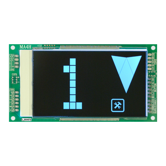
RGB LCD DISPLAY BOARD
PROGRAMMING
AND
INSTALLATION
MANUAL
VERSION: 1.2
AYBEY ELEKTRONIK GmbH
Lothringer Allee 2 44805 Bochum Germany
T: +49 (0) 234 687 36 82 9 G: +49 (0) 176 404 30 68 4
e-mail: support@aybey-elektronik.de
www.aybey-elektronik.de
F/7.5.5.02.89 R:2
CCL
1
Advertisement
Table of Contents

Subscribe to Our Youtube Channel
Related Manuals for Aybey Elektronik CCL-S


Summary of Contents for Aybey Elektronik CCL-S
- Page 1 CCL-S / CCT / CCL-P CUSTOM DESIGN RGB LCD DISPLAY BOARD PROGRAMMING INSTALLATION MANUAL VERSION: 1.2 AYBEY ELEKTRONIK GmbH Lothringer Allee 2 44805 Bochum Germany T: +49 (0) 234 687 36 82 9 G: +49 (0) 176 404 30 68 4 e-mail: support@aybey-elektronik.de...
- Page 2 It needs 12-24V DC supply. CCL-S and CCT gets all information from CANBus. CCL-S is used for fault tolerant applications, CCT is used for high speed applications. CCL- P can be applied up to 64 stops with 6 gray/binary code inputs as M0,…,M5 or counter systems inputs as M0, 817, 818 and 7-Segment inputs.
- Page 3 PROGRAMMING On board, there are 3 buttons named as INC (↑), DEC (↓) and ENT. ENT button is used to enter and exit to/from programming mode, to approve and to save settings. INC (↑) and DEC (↓) buttons are used to increase and decrease current value and move up and down in menu. FLOOR DISPLAY SETTINGS (Only in Parallel Mode CCL-P) Push and hold ENT button a few second to enter programming mode where arrows and busy icon always blink to distinguish it from normal mode.
- Page 4 Simulation ID DEFINITION (Only in CANBus CCL-S/CCT) ID information (0 to 63) of CCL-S/CCT board must be set to identify address of it in CANBus communication. ID letters on display shows this menu. FLOOR COUNT DEFINITION Floor count at simulation mode can be set in this menu. SF letters on display shows this menu.
- Page 5 NEW COLOR DEFINITION There are 50 free user definable color in system to set floor or signal color. Press and hold ENT and DEC (↓) buttons to set a new color to your system. When you enter Color Definition Mode, “CM” letters displays.
Need help?
Do you have a question about the CCL-S and is the answer not in the manual?
Questions and answers