Advertisement
Quick Links
600928300000
It is of vital importance, before attempting to operate
your engine, to read the general 'SAFETY INSTRUCTIONS
AND WARNINGS' in the following section and to strictly
adhere to the advice contained therein.
Also, please study the entire contents of this
instruction manual, so as to familiarize yourself with
the controls and other features of the engine.
SAFETY INSTRUCTIONS AND WARNINGS ABOUT YOUR O.S.ENGINE
Remember that your engine is not a " toy ", but a
highly efficient internal-combustion machine whose
power is capable of harming you, or others, if it is
misused. As owner, you, alone, are responsible for
the safe operation of your engine, so act with
discretion and care at all times. If at some future
date, your O.S. engine is acquired by another
person, we would respectfully request that these
instructions are also passed on to its new owner.
The advice which follows is grouped under two
headings according to the degree of damage or
danger which might arise through misuse or neglect.
WARNINGS
These cover events which might involve serious
(in extreme circumstances, even fatal) injury.
NOTES
These cover the many other possibilities, generally less
obvious sources of danger, but which, under certain
circumstances, may also cause damage or injury.
WARNINGS
Never touch, or allow any object to come
into contact with, the rotating parts.
Model engine fuel is poisonous. Do not allow
it to come into contact with the eyes or mouth.
Always store it in a clearly marked container
and out of the reach of children.
Notes on installing cooling fan and clutch
Do not use a tool which
locks piston when installing
a cooling-fan and clutch, or
top of the piston may be
damaged. Also, do not insert
a screw driver or the similar
into the exhaust port.
It is recommended to use
Crankshaft Clamp 37 (Code
No.71530600) available as an
optional tool.
Do not grip the engine mounting beams with a
vise, or the crankcase will be distorted which
will result in engine breaking.
Vise
Beam Mount
NOTES WHEN APPLYING AN ELECTRIC STARTER
Because of this initial tightness, a standard
electric starter may have difficulty in rotating the
engine when cold, before it has been adequately
run-in. In this case, use a high-torque type starter.
Do not over-prime. This could cause a hydraulic
lock and damage the engine on application of the
electric starter.
If over-primed, remove glowplug, close needle-valve
and apply starter to pump out surplus fuel. Cover
the head with a rag to prevent pumped out fuel
from getting into your eyes.
37SZ-H
MAX-
Model engine fuel is also highly flammable.
Keep it away from open flame, excessive
heat, sources of sparks, or anything else
which might ignite it. Do not smoke or allow
anyone else to smoke, near to it.
Model engines generate considerable
heat. Do not touch any part of your
engine until it has cooled. Contact with
the muffler (silencer), cylinder head or
exhaust header pipe, in particular, may
result in a serious burn.
Never operate your engine in an enclosed space.
Model engines, like automobile engines, exhaust
deadly carbon-monoxide. Run your engine only
in an open area.
NOTES
This engine was designed for model helicopters.
Do not attempt to use it for any other purpose.
Mount the engine in your model securely, following
the manufacturers' recommendations, using appropriate
screws and locknuts.
Install an effective silencer (muffler). Frequent close
exposure to a noisy exhaust (especially in the case of
the more powerful high-speed engines) may eventually
impair your hearing and such noise is also likely to
cause annoyance to others over a wide area.
Check the linkage to the throttle arm before each
flight.
Avoid sudden high r.p.m. immediately after the
engine is started, as the clutch will engage and you
may be struck by the rotor.
Linking the throttle servo to the carburetor
Link the throttle servo to the carburetor using
the throttle lever supplied. Throttle control rod
A and B should be equal length. Set the
linkage so that the servo output lever and
throttle lever are parallel when the throttle
stick on the transmitter is at middle position.
Installing hole intervals on the F lever and on
the J lever are different. Decide the lever to
use according to the servo used. Be sure to
cut off another lever to avoid any interference.
INTRODUCTION
This is a high performance engine designed for
small-sized radio-controlled helicopters.
Since the mounting bolt pattern of the engine as
well as silencer is the same as those of the 32SX-H,
it can be directly replaced with the 32SX-H and most
of other 32-39 size engines. This powerful engine is
suitable for sport flight as well as 3D flight.
With some models, needle interferes the body and
working on the body to avoid this would be required.
STANDARD ACCESSOIES
Glow Plug No.8
O.S. No.8 glowplug is
supplied with the engine
Throttle Lever Assembly
Throttle lever is not installed on the carburetor
when the engine leaves the factory.
Install it before using the engine.
RING
B
F
F
A
28
A=B
34
NOTE
After starting the engine, carry out any needle-valve
readjustments after stopping the rotor by closing the
throttle to the lowest r.p.m..
Stop the engine before attempting to make other
adjustments to the carburetor.
Use an electric starter. The wearing of safety
glasses is also strongly recommended.
Press the rotor head down securely.
Take care that the glow plug clip or battery leads do
not come into contact with rotating parts.
Adjust the throttle linkage so that the engine stops
when the throttle stick and trim lever on the
transmitter are fully retarded. Alternatively, the
engine may be stopped by cutting off the fuel
supply. Never try to stop the engine physically.
Take care that loose clothing (ties, shirt sleeves,
scarves etc.) do not come into contact with the rotor.
Do not carry loose objects (such as pencils, screwdriv-
ers, etc.) in a shirt pocket from where they could fall
through the rotor disc.
For their safety, keep all onlookers (especially small
children) well back (at least 20 feet or 6 metres) when
preparing your model for flight. If you have to carry the
model to the take-off point with the engine running, be
especially cautious. Hold the rotor securely and keep
well clear of spectators.
Warning! lmmediately after a glowplug-ignition
engine has been run and is still warm, conditions
sometimes exist whereby it is just possible for the
engine to restart when turned over WITHOUT the
glowplug battery being reconnected. Remember this
if you wish to avoid the risk of accidents.
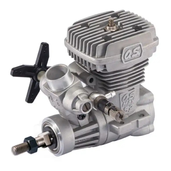
ENGINE PARTS NAME
Heatsink Head
Carburetor
Type 20M
Thrust Washer
Crankshaft
Propeller nut
Rotor Guide Screw
Mixture Control Valve
Throttle Lever
Carburetor Gasket
BEFORE STARTING
Tools, accessories, etc.The following items are necessary
for operating the engine.
Items necessary for starting
Battery leads
These are used to conduct current from
the battery to the glowplug. Basically, two
leads, with clips, are required, but, for
greater conve-nience, twin leads with
special glowplug connectors, as shown on
the right, are commercially available.
Glowplug battery
The power source for heating the glowplug may be
either a large heavy-duty 1.5volt dry cell, Ni-cd battery
or glowplug Igniter.
1.5 volt dry cell
Glowplug
Cover Plate
Beam Mount
Crankcase
Fuel Inlet
Needle Valve
Battery leads
glowplug Igniter
Advertisement

Related Manuals for O.S. engine MAX-37SZ-H RING


Summary of Contents for O.S. engine MAX-37SZ-H RING
- Page 1 If at some future engine may be stopped by cutting off the fuel deadly carbon-monoxide. Run your engine only date, your O.S. engine is acquired by another supply. Never try to stop the engine physically. in an open area.
- Page 2 In the course of making carburetor adjustments, it is INSTALLATION OF THE ENGINE just possible that the Mixture Control Valve may be The under-surfaces of all O.S. engine beam mounting inadvertently screwed in or out too far and thereby lugs are precision machined flat and exactyly parallel moved beyond its effective adjustment range.
- Page 3 Preparation of starting SUBSEQUENT READJUSTMENTS Warm the engine by allowing it to idle for about 30 Make sure that the transmitter seconds. If the engine stops, advance the throttle Once the engine has been run-in and the carburetor throttle stick is at the fully closed trim lever slightly to increase the idle rpm.
- Page 4 Weight (Engine) 293 g / 10.34 oz. 1/4-28UNF 30.6 45.9 21.3 6-15 3-Chome Imagawa Higashisumiyoshi-ku Osaka 546-0003, Japan TEL. (06) 6702-0225 FAX. (06) 6704-2722 http://www.os-engines.co.jp 121401 Copyright 2013 by O.S. Engine Mfg. Co., Ltd. All rights reserved. Printed in CHINA.