
Related Manuals for phase II+ PHT-1800


Summary of Contents for phase II+ PHT-1800
- Page 1 Model No. PHT-1800 Operation Manual 283 Veterans Blvd Carlstadt, NJ. U.S.A 07072 Phone: (201) 933-6300 Fax: (201) 933-3801 www.phase2plus.com...
-
Page 2: Table Of Contents
1 Overview........................3 1.1 Advantages ........................3 1.2 Main Application &Testing Range ................... 3 1.2.1 Main Application ......................3 1.2.2 Testing Range......................... 3 1.3 Technical Specifications ....................4 1.4 Configuration ........................5 1.5 Working Conditions ......................5 2 Structure Feature &Testing Principle ..............6 2.1 Structure Feature ....................... - Page 3 6.1 Impact Device Maintenance ................... 19 6.2 Instrument Maintenance Program ................... 19 6.3 Fault Analysis & Evaluation ................... 19 6.4 Notice of Transport and Storage Conditions ....Error! Bookmark not defined. APPENDIX ......................... 20 Table 1 ..........................20 Table 2 ..........................21 Table 3 ..........................
-
Page 4: Overview
1 Overview 1.1 Advantages Wide measuring range. Based on the principle of Leeb hardness testing theory. Capable of measuring Leeb hardness of all metallic materials. Large screen LCD, showing all functions and parameters. With background light. Seven impact devices are available for special application. Automatic identification of impact device upon plug in. -
Page 5: Technical Specifications
1.3 Technical Specifications Error and repeatability of displayed value see Table1-1 below. Table 1-1 Type of Hardness value of Leeb Error of displayed Repeatability impact device standard hardness block value ±6 HLD 760±30HLD 6 HLD 10 HLD ±10 HLD 530±40HLD ±6 HLDC 760±30HLDC... -
Page 6: Configuration
1.4 Configuration Table 1-2 Item Quantity Remarks Standard Main unit Configuration D type impact device With cable Standard test block Cleaning brush (I) Small support ring Alkaline battery AA size Manual Instrument package case Optional Cleaning brush (II) For use with G Configuration type impact... -
Page 7: Structure Feature &Testing Principle
2 Structure Feature &Testing Principle 2.1 Structure Feature HARDNESS GAUGE POWER: 2 X 1.5V 4- Nodular Cast Iron 5- Cast Aluminum Alloys Material Option: 6- Copper-Zinc Alloys 0- Steel and Cast Steel 7- Copper-Aluminum 1- Cold Work Tool Steel 2- Stainless Steel 8- Wrought Copper 3- Gray Cast Iron 9- Wrought Steel... -
Page 8: Different Types Of Impact Device
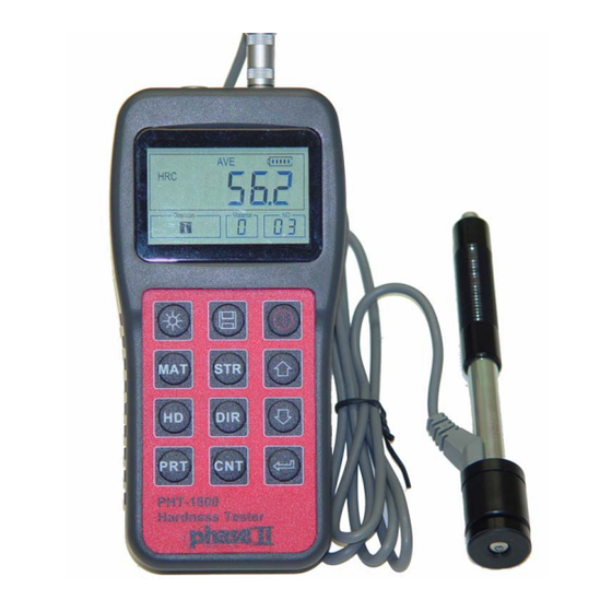
2.1.2 Different Types of Impact Device D+15 2.2 Main Screen Below is the main display screen: Average Icon Memory Icon Battery Info Measured Value Hardness Scale Impact Times Direction Material No Instruction of the Main Display Screen: : The present presetting material. Material :... -
Page 9: Keypad Definitions
prompting). “ -HI-” means over conversion value or measure range. “ -LO-” means lower than conversion value or measure range. : Times that have been impacted. Impact times : It will appear when showing the mean value of the measured Average Icon values after reaching the presetting impact times. -
Page 10: Leeb Hardness Testing Principle
2.4 Leeb Hardness Testing Principle It is defined as the quotient of an impact body’s rebound velocity over its impact velocity, multiplied by 1000. Harder materials produce a higher rebound velocity than softer materials. For a specific group of material (e.g. steel, aluminum. etc.). Leeb hardness value represents a direct relationship to its hardness properties. -
Page 11: Preparation Of The Sample Surface
3.3 Preparation of the Sample Surface Preparation for sample surface should conform to the relative requirement in Appendix Table 3. Test surfaces should be at or close to room temperature for optimal performance To eliminate hardness errors resulting from the roughness of a sample’s surface when using impact device D, DC or D+15, the test surface should be polished until its roughness Ra is no more than 2m. - Page 12 Coupling. Light-weight sample must be firmly coupled with a heavy base plate. Both coupled surface must be flat and smooth. The impact direction must be vertical to the coupled surface. When the sample is a big plate, or long rod, it can be deformed and become unstable, even though its weight and thickness is within allowable ranges, and accordingly, the test value may not be accurate.
-
Page 13: Testing Program
4 Testing Program 4.1 Start-Up Insert the plug of the impact device into the socket of impact device on the instrument. Press the key,now power is on. The instrument is in working mode. 4.2 Loading Pushing the loading-tube downwards until contact is felt. Then allow it to slowly return to the starting position or using other method locking the impact body. -
Page 14: Read Measured Value
Table 4-1 Type of Impact Distance of center of the Distance of center of the Device two indentations indentation to sample edge Not less than (mm) Not less than (mm) D、DC D+15 4.5 Read Measured Value After each impact operation, the LCD will display the current measured value, impact times plus one, the buzzer will alert you if the measured value is not within the valid range. -
Page 15: Operation Detail
5 Operation Detail 5.1 Power On/Off Press to power on the instrument. Be sure to plug in the impact device before powering on. The system would automatically detect the type of the impact device during power up, and would display this information on the screen. -
Page 16: Hardness/Strength Testing
In strength testing, the following materials are selectable: Mild Steel、High-Carbon Steel、Cr Steel、Cr-V Steel、Cr-Ni Steel、Cr-Mo Steel、Cr-Ni-Mo Steel、Cr-Mn-Si Steel、 Super Strength Steel and Stainless Steel. The relationship between the material number displayed on the instrument screen and the material is as follows: Table 5-2 Material No Material... -
Page 17: Data Logging
5.6 Data logging At most one hundred files (F00-F99, one group as one file) can be stored inside the gauge. By simply pressing the key after a new measurement finishes-the screen showing the “AVE” icon, the measured hardness/strength group values will be saved to memory. The new saved file is appended as the last file of the memory. -
Page 18: System Reset
mini-printer. Before printing, please insert one connection plug of the print cable (Optional part) into the socket on the upper left of the main body, and insert the other plug into the communication socket of the mini-printer. You can print out the measurement result immediately after each testing process, by easily pressing the key. -
Page 19: Connecting To A Computer
Please properly dispose of used batteries accordingly. 5.12 Connecting to a Computer The Instrument is equipped with a USB serial port. Using the output cable the gauge has the ability to connect to a computer, or external storage device. Measurement data stored in the memory of the gauge can be transferred to the computer through the USB port. -
Page 20: Maintenance & Servicing
6 Maintenance & Servicing 6.1 Impact Device Maintenance After the impact device has been used for 1000--2000 times, please use the nylon brush provided to clean the guide tube and impact body. When cleaning the guide tube, unscrew the support ring first, then take out the impact body, spiral the nylon brush in counter-clock direction into the bottom of guide tube and take it out for 5 times, and then install the impact body and support ring again. - Page 21 APPENDIX Table 1 Impact device Material Method D/DC D+15 20~ 19.3~ 20.0~ 20.6~ 22.4~70.7 68.5 67.9 69.5 68.2 38.4~ 47.7~ 37.0~ 99.6 99.9 99.9 59.1~ Steel and cast 61.7~88.0 steel 85.8 127~ 80~638 80~683 90~646 83~663 81~646 83~976 80~937 80~996 84~1042 80~950 32.2~...
- Page 22 Table 2: Leeb to Tensile Strength Conversion Chart: This is an Approximation only! Strength σ Material (MPa) Mild steel 350~522 374~780 High-Carbon steel 500~710 737~1670 Cr steel 500~730 707~1829 Cr-V steel 500~750 704~1980 Cr-Ni steel 500~750 763~2007 Cr-Mo steel 500~738 721~1875 Cr-Ni-Mo steel 540~738...
- Page 23 Table 3 Type of impact device DC(D)/DL D+15 Impacting energy 11mJ 11mJ 2.7mJ 90mJ 11mJ Mass of impact body 5.5g/7.2g 7.8g 3.0g 20.0g 5.5g Test tip hardness: 1600HV 1600HV 1600HV 1600HV 5000HV Dia. Test tip: Material of test tip: Tungsten Tungsten Tungsten Tungsten...
- Page 24 Optional 12pc Support Ring Set Part No. PHT1500-300 Type Sketch of Remarks non-conventional Supporting ring For testing cylindrical outside Z10-15 surface R10~R15 For testing cylindrical outside Z14.5-30 surface R14.5~R30 For testing cylindrical outside Z25-50 surface R25~R50 For testing cylindrical inside HZ11-13 surface R11~R13 For testing cylindrical inside...
- Page 25 Main Headquarters: U.S.A Phase II Machine & Tool, Inc. 283 Veterans Blvd Carlstadt, NJ. 07072 USA Tel: (201) 933-6300 Fax: (201) 933-3801 General E-Mail: phase2@comcast.net BEIJING, CHINA Phase II Measuring Instruments (Beijing) Ltd. Room 1204,Bldg 13,Yong Tai Yuan,Qing He,Haidian District, Beijing 100192,China Tel:+86-10-82752121 Fax:+86-10-82750352 General E-mail:...
Need help?
Do you have a question about the PHT-1800 and is the answer not in the manual?
Questions and answers