Advertisement
Advertisement
Table of Contents

Related Manuals for phase II+ SRG-2000


Summary of Contents for phase II+ SRG-2000
- Page 1 Model No. SRG‐2000 INSTRUCTION MANUAL Manual should be read prior to operation!
- Page 2 CONTENTS 1) GENERAL 2) WORK PRINCIPLE AND STRUCTURE FEATURES 3) MAJOR TECHNICAL PARAMETERS 4) USE AND OPERATION 5) MAINTENANCE AND REPAIR APPENDIX: RECOMMENDED SAMPLING LENGTH 21 Industrial Ave Upper Saddle River, NJ. 07458 Tel: (201)962-7373 Fax: (201)962-8353 E-mail: info@phase2plus.com WebSite: http://phase2plus.com...
- Page 3 1) GENERAL The Phase II model no. SRG‐2000 Mini Surface Roughness Tester is a next generation of product developed for the Phase II Metrology Group that features high accuracy, a wide range of application, simple operation and stable performance. It is widely applicable in testing surfaces of all kinds of metals and non‐metals. Integrating the sensor with its mainframe, its a hand‐held set especially suited for use on any production site. 2) WORKING PRINCIPLE AND STRUCTURE FEATURES 2.1) WORKING PRINCIPLE When the motorized sensor is making a linear uniform motion along the test surface, the contact stylus being perpendicular to the work surface, moves up and down with the work surface. Its motion is converted into electric signals, which are amplified, filtered and transformed into digital signals through a/d. The signals are then processed by the CPU into Ra and Rz values before being displayed on the screen. 2.2) STRUCTURAL FEATURES 2.2A) BASIC SETUP: FOR OUTWARD APPEARANCE, SEE FIGURE 1. Base Instrument 1 UNIT Battery Charger 1 UNIT Calibration Standard/Base 1 UNIT NEW! Small Round Parts Vise Now check surface finish on these difficult to test parts with your SRG‐2000! Part No. SRG2000‐VISE 21 Industrial Ave Upper Saddle River, NJ. 07458 Tel: (201)962-7373 Fax: (201)962-8353 E-mail: info@phase2plus.com ...
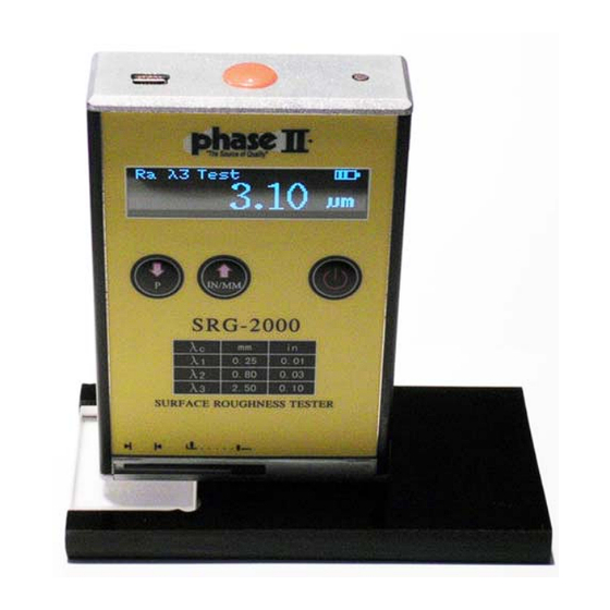
- Page 4 FIGURE 2: STRUCTURE OF MAINFRAME 1) Start Test Button 2) Lcd Screen 3) Scale Selection / Up 4) Inch/Metric Conversion / Down 5) Power Switch 6) Charging Socket 7) Stylus Mark 8) Stylus Protective Guard 21 Industrial Ave Upper Saddle River, NJ. 07458 Tel: (201)962-7373 Fax: (201)962-8353 E-mail: info@phase2plus.com WebSite: http://phase2plus.com...
- Page 5 ) MAJOR TECHNICAL PARAMETERS ROUGHNESS PARAMETERS Ra, Rz, Rq, Rt MEASURING RANGE RA: 0.05‐10.0µM RZ: 0.1 ‐ 50µM Rq :0.05 ~ 10.0µm Rt: 0.1 ~ 50µm CUT‐OFF LENGTHS 0.25, 0.80, 2.50 FILTER RC ANALOG TRACING LENGTH 0.23IN (6MM) TRACING SPEED 0.04IN/SECOND (1.0MM/SECOND) ACCURACY +/‐12% of known value PICK UP STYLUS PIEZO‐ELECTRIC TRACER TIP DIAMOND, RADIUS 10µM +/‐ 1µM OPERATING TEMPERATURE 32‐104 DEGREES F (0‐40 DEGREES C) POWER 3.7v Lithium ion Battery CONTACT FORCE ON PROBE <0.5N STATIC MEASURING FORCE OF SENSOR STYLUS < 0.016N DIMENSIONS 106 X 70 X 24mm WEIGHT 0.4LBS (200G) 4) USE AND OPERATION 4.1) OPERATION: POWER ON THE DEVICE. Press and hold the Red Power button on the front panel for 1 second. After a “beep” sound, the device is ready to work. The large LCD display will show the measuring parameters and sampling length of the previous test. Before taking a test, choose the desired parameter Ra, Rz, Rq, or Rt and proper sampling length 2.5, 0.8 or 0.25 (for sampling length option, consult the appendix).
- Page 6 POINTS FOR ATTENTION: While the stylus is in motion, you must keep the device even and steady so as not to affect the accuracy of the reading. Before the sensor returns to the original position, the device will not respond to any operation until the measurement is completed. 4.2) CALIBRATION When abnormal errors are found, the standard sample block may be used for calibration. The Ra values of the sample block used for calibration, range from 0.1 µM ‐ 10µM. METHOD: with the tester in metric mode and the power off, press the red Start button on top while pressing the Power button together. When a beep sounds, release the button and the device enters its calibration mode. The LCD screen should read “CAL” and there will be a Ra value on the display. If this value doesn’t match your test sample then you must adjust it by pressing the up/down arrow buttons on the keypad. Press the Start button on top and the unit will begin calibrating itself. The value displayed at the end of this process should fall within the allowable tolerance of your test sample. To complete the process. Power the unit off. This will now save the new calibration. Normal measurements can resume at this time. 4.3) CONVERTING IN/MM Press and hold the keypad for about 1 second. The system will convert from Metric to English or English to Metric 4.5) LOW VOLTAGE INDICATOR When the battery symbol is near empty then its time to recharge the SRG‐2000. The tester must be recharged before further usage. 4.6) RECHARGING Plug the charger into the socket of the tester. A full recharge should take between 3‐5 hours. If needed, the tester can function while charging. 5) MAINTENANCE AND REPAIR 5.1) MAINTENANCE Avoid collision, violent shock, heavy dust, dampness, oil and a strong magnetic field. The Piezo‐electric pick up stylus with diamond tip is extremely sensitive and accurate. After each use, make sure that the supplied protective cover goes on this tip after each use. Damage to this tip will result in false and erroneous readings. 5.2) REPAIR ALL REPAIRS MUST BE DONE THROUGH THE PHASE II SERVICE DEPARTMENT. A return authorization number must is mandatory in order for a defective tester to be accepted for repair and/or replacement. All testers must be accompanied by your warranty card or serial number. Complete description of problem and a contact person for authorization of repairs must be supplied as well. ANY ATTEMPT AT HOME REPAIR WILL AUTOMATICALLY VOID THE STATED WARRANTY! NO EXCEPTIONS! 21 Industrial Ave Upper Saddle River, NJ. 07458 Tel: (201)962-7373 ...
- Page 7 Appendix: Recommended Sampling Length. Ra (µm) Rz (µm) SAMPLING LENGTH >40 ‐ 80 >160 ‐ 320 >20 ‐ 40 >80 ‐ 160 >10 ‐ 20 >40 ‐ 80 >5 ‐ 10 20 ‐ 40 2.5 >2.5 ‐ 5 >10 ‐ 20 2.5 >1.25 ‐ 2.5 >6.3 ‐ 0 0.8 >0.63 ‐ 1.25 >3.2 ‐ 6.3 0.8 >0.32 ‐ 0.63 >1.6 ‐ 3.2 0.8 >0.25 ‐ 0.32 >1.25 ‐ 1.6 0.25 >0.20 ‐ 0.25 >1.0 ‐ 1.25 0.25 >0.16 ‐ 0.20 >0.8 ‐ 1.0 0.25 >0.125 ‐ 0.16 >0.63 ‐ 0.8 0.25 >0.1 ‐ 0.125 >0.5 ‐ 0.63 0.25 >0.08 ‐ 0.1 >0.4 ‐ 0.5 0.25...
- Page 8 Main Headquarters: U.S.A Phase II Machine & Tool, Inc. 21 Industrial Ave Upper Saddle River, NJ. 07458 USA Tel: (201) 962‐7373 Fax: (201) 962‐8353 General E‐Mail: info@phase2plus.com BEIJING, CHINA Phase II Measuring Instruments (Beijing) Ltd. Room 301, Bldg 2 Qing Yuan Xi Li, Haidian District, Beijing 100192,China Tel:+86‐10‐59792409 Fax:+86‐10‐59814851 General E‐mail: info@phase2china.com.cn MEXICO Phase II de Mexico Calle A No. 4 Promer Piso Col. San Marcos Azcapotzalco C.P 02020 Mexico Tel: 011‐525‐5538‐39771 Fax: same General E‐mail: phase2mexico@hotmail.com VENEZUELA Phase II Herramientas Universales EDCM. CA. Av. Francisco Lazo Marti CC Plaza Santa Monica PB Local Santa Monica, Caracas 1040 Venezuela Tel: 212‐690‐28‐21 Fax: 212‐693‐29‐16 E‐mail: edcphm@movistar.net 21 Industrial Ave Upper Saddle River, NJ. 07458 Tel: (201)962-7373 Fax: (201)962-8353 E-mail: info@phase2plus.com ...
Need help?
Do you have a question about the SRG-2000 and is the answer not in the manual?
Questions and answers