
Related Manuals for Dell OptiPlex 7070


Summary of Contents for Dell OptiPlex 7070
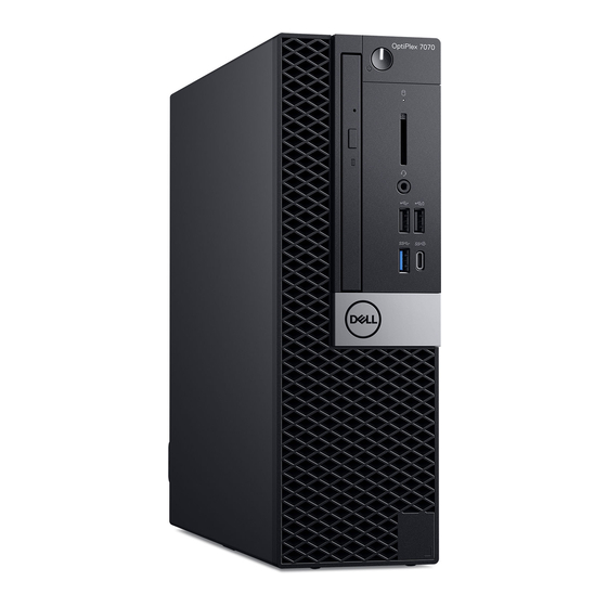
- Page 1 Dell OptiPlex 7070 Small Form Factor Service Manual Regulatory Model: D11S Regulatory Type: D11S004 March 2021 Rev. A01...
- Page 2 A WARNING indicates a potential for property damage, personal injury, or death. © 2016 - 2020 Dell Inc. or its subsidiaries. All rights reserved. Dell, EMC, and other trademarks are trademarks of Dell Inc. or its subsidiaries. Other trademarks may be trademarks of their respective owners.
-
Page 3: Table Of Contents
Contents Chapter 1: Working on your computer................... 5 Safety instructions................................5 Before working inside your computer........................5 Safety precautions................................ 6 Electrostatic discharge—ESD protection....................... 6 ESD field service kit ..............................7 Transporting sensitive components.......................... 8 After working inside your computer..........................8 Chapter 2: Technology and components..................9 DDR4.......................................9 USB features..................................10 USB Type-C..................................12... - Page 4 Removing system board............................60 Installing the system board............................64 Chapter 5: Troubleshooting......................68 Enhanced Pre-Boot System Assessment — ePSA diagnostics................68 Running the ePSA Diagnostics..........................68 Diagnostics..................................68 Diagnostic error messages.............................. 70 System error messages..............................73 Chapter 6: Getting help....................... 75 Contacting Dell...................................75 Contents...
-
Page 5: Chapter 1: Working On Your Computer
Damage due to servicing that is not authorized by Dell is not covered by your warranty. Read and follow the safety instructions that came with the product. -
Page 6: Safety Precautions
ESD protection is an increasing concern. Due to the increased density of semiconductors used in recent Dell products, the sensitivity to static damage is now higher than in previous Dell products. For this reason, some previously approved methods of handling parts are no longer applicable. -
Page 7: Esd Field Service Kit
It is recommended that all field service technicians use the traditional wired ESD grounding wrist strap and protective anti-static mat at all times when servicing Dell products. In addition, it is critical that technicians keep sensitive parts separate from all insulator parts while performing service and that they use anti-static bags for transporting sensitive components. -
Page 8: Transporting Sensitive Components
Transporting sensitive components When transporting ESD sensitive components such as replacement parts or parts to be returned to Dell, it is critical to place these parts in anti-static bags for safe transport. Lifting equipment Adhere to the following guidelines when lifting heavy weight equipment: CAUTION: Do not lift greater than 50 pounds. -
Page 9: Chapter 2: Technology And Components
Technology and components This chapter details the technology and components available in the system. Topics: • DDR4 • USB features • USB Type-C • Advantages of DisplayPort over USB Type-C • HDMI 2.0 • Intel Optane memory DDR4 DDR4 (double data rate fourth generation) memory is a higher-speed successor to the DDR2 and DDR3 technologies and allows up to 512 GB in capacity, compared to the DDR3's maximum of 128 GB per DIMM. -
Page 10: Usb Features
Figure 2. Thickness difference Curved edge DDR4 modules feature a curved edge to help with insertion and alleviate stress on the PCB during memory installation. Figure 3. Curved edge Memory Errors Memory errors on the system display the new ON-FLASH-FLASH or ON-FLASH-ON failure code. If all memory fails, the LCD does not turn on. - Page 11 ● Full-duplex data transfers and support for new transfer types ● Backward USB 2.0 compatibility ● New connectors and cable The topics below cover some of the most commonly asked questions regarding USB 3.0/USB 3.1 Gen 1. Speed Currently, there are 3 speed modes defined by the latest USB 3.0/USB 3.1 Gen 1 specification. They are Super-Speed, Hi-Speed and Full-Speed.
-
Page 12: Usb Type-C
● USB 3.0/USB 3.1 Gen 1 Drive Docks & Adapters ● USB 3.0/USB 3.1 Gen 1 Flash Drives & Readers ● USB 3.0/USB 3.1 Gen 1 Solid-state Drives ● USB 3.0/USB 3.1 Gen 1 RAIDs ● Optical Media Drives ● Multimedia Devices ●... -
Page 13: Hdmi 2.0
● Backwards compatibility to VGA, DVI with adaptors ● SuperSpeed USB (USB 3.1) data ● Supports HDMI 2.0a and is backwards compatible with previous versions HDMI 2.0 This topic explains the HDMI 2.0 and its features along with the advantages. HDMI (High-Definition Multimedia Interface) is an industry-supported, uncompressed, all-digital audio/video interface. -
Page 14: Enabling Intel Optane Memory
Table 2. Intel Optane memory specifications Feature Specifications Interface PCIe 3x2 NVMe 1.1 Connector M.2 card slot (2230/2280) Configurations supported ● 7th Generation or higher Intel Core i3/i5/i7 processor ● Windows 10 64-bit version 1607 or higher ● Intel Rapid Storage Technology driver version 15.9.1.1018 or higher Capacity 32 GB... -
Page 15: Chapter 3: Major Components Of Your System
Major components of your system 1. Side cover 2. Expansion card Major components of your system... - Page 16 16. Power supply unit NOTE: Dell provides a list of components and their part numbers for the original system configuration purchased. These parts are available according to warranty coverages purchased by the customer. Contact your Dell sales representative for purchase options.
-
Page 17: Chapter 4: Removing And Installing Components
Removing and installing components NOTE: The images in this document may differ from your computer depending on the configuration you ordered. Topics: • Side cover • Expansion card • Coin cell battery • Hard drive assembly • Hard drive • Bezel •... -
Page 18: Installing The Side Cover
Installing the side cover 1. Place the cover on the system and slide the cover until it clicks into place [1]. 2. The release latch automatically locks the side cover to the system [2]. Removing and installing components... -
Page 19: Expansion Card
3. Follow the procedure in After working inside your computer Expansion card Removing expansion card 1. Follow the procedure in Before working inside your computer. 2. Remove the Side cover. 3. To remove the expansion card: a. Pull the metal tab to open the expansion card latch [1]. b. -
Page 20: Installing The Expansion Card
Installing the expansion card NOTE: To remove the PCIe brackets, push the bracket upwards from the inside of your computer to release it and then lift the bracket away from your computer. Insert a screwdriver in the hole of a PCIe bracket and push hard to release the bracket [3], and then lift the bracket out from your computer. -
Page 21: Coin Cell Battery
4. Install the Side cover. 5. Follow the procedure in After working inside your computer. Coin cell battery Removing coin cell battery CAUTION: Removing coin cell battery may reset the motherboard. 1. Follow the procedure in Before working inside your computer. -
Page 22: Installing The Coin Cell Battery
Installing the coin cell battery 1. Place the coin cell battery with "+" sign facing up in the slot on the system board [1]. 2. Press the battery into the connector until it locks into place [2]. Removing and installing components... -
Page 23: Hard Drive Assembly
3. Install the: Expansion cards Side cover 4. Follow the procedure in After working inside your computer. Hard drive assembly Depending on the configuration you choose, you will have either one 3.5–inch hard drive assembly or two 2.5–inch hard drive assembly. -
Page 24: Installing The Hard Drive Assembly
Installing the hard drive assembly 1. Align the tabs on the hard drive assembly with the slots on the chassis at 30 degree angle [1]. 2. Press the hard drive assembly so that it gets secured to the hard drive and optical drive cage [2]. 3. -
Page 25: Hard Drive
4. Install the Side cover. 5. Follow the procedure in After working inside your computer. Hard drive Removing the hard drive NOTE: For configurations shipped with 3.5-inch HDD, follow the same procedure to remove the HDD from its bracket. 1. Follow the procedure in Before working inside your computer. -
Page 26: Installing The Hard Drive
Installing the hard drive NOTE: For configurations shipped with 3.5-inch HDD, follow the same procedure to install the HDD into its bracket. 1. Insert the holes on one side of the hard disk into the pins on the hard drive bracket [1], and then place the hard drive into the bracket such that the pins on other side of the bracket is aligned with the holes on the hard drive [2]. -
Page 27: Installing Front Bezel
Installing front bezel 1. Align the bezel and insert the retention tabs on the bezel into the slots on the system. 2. Press the bezel until the tabs clicks into place. 3. Install the Side cover. Removing and installing components... -
Page 28: Hard Drive And Optical Drive Module
4. Follow the procedure in After working inside your computer. Hard drive and optical drive module Removing the hard drive and optical drive module 1. Follow the procedure in Before working inside your computer. 2. Remove the: Side cover Front bezel HDD assembly 3. - Page 29 4. To remove the hard drive and optical drive module: a. Disconnect the optical drive data cable and optical drive power cable from the connectors on the optical drive [1, 2]. b. Slide and lift the hard drive and optical drive module from the system [3]. Removing and installing components...
-
Page 30: Installing The Hard Drive And Optical Drive Module
Installing the hard drive and optical drive module 1. Insert the tabs on the hard drive and optical drive module into the slot on the system at 30 degree angle [1]. 2. Connect the optical drive data cable and power cable to the connectors on the optical drive [2, 3]. Removing and installing components... - Page 31 3. Lower the hard drive and optical drive module so that it is placed in its slot [1]. 4. Slide the release tab to lock the module [2]. Removing and installing components...
- Page 32 5. Route the hard drive data and power cables through the HDD-ODD release tab [1]. 6. Route the optical drive data cable and power cable through the retention clips [2]. Removing and installing components...
-
Page 33: Optical Drive
7. Install the: HDD assembly Front bezel Side cover 8. Follow the procedure in After working inside your computer. Optical drive Removing the optical drive 1. Follow the procedure in Before working inside your computer. 2. Remove the: Side cover Front bezel 3. - Page 34 b. Slide the release tab to unlock the hard drive and optical module [1]. c. Lift the hard drive and optical module [2]. Removing and installing components...
- Page 35 d. Disconnect the optical drive data cable and optical drive power cable from the connectors on the optical drive [1, 2] and lower the hard drive and optical module until it is seated. Removing and installing components...
- Page 36 e. Push the release latch on the optical drive [1] and pull the optical drive out from the system [3]. Removing and installing components...
-
Page 37: Installing The Optical Drive
Installing the optical drive 1. Slide the optical drive into its slot in the system [1]. 2. Slide the release tab to unlock the hard drive and optical drive module [2]. Removing and installing components... - Page 38 3. Lift the hard drive and optical module [1], connect the optical drive data cable and power cable to the connectors on the optical drive [2, 3]. Removing and installing components...
- Page 39 4. Connect the hard drive data cable and hard drive power cable to the connectors on the hard drive [1,2]. Removing and installing components...
-
Page 40: Memory Module
5. Slide the release tab to lock the module [2]. 6. Install the: Front bezel Side cover 7. Follow the procedure in After working inside your computer. Memory module Removing memory module 1. Follow the procedure in Before working inside your computer. -
Page 41: Installing The Memory Module
Installing the memory module 1. Align the notch on the memory module with the tab on the memory module connector. 2. Insert the memory module into the memory module socket [1]. 3. Press the memory module until the memory module retention tabs click into place [2]. Removing and installing components... -
Page 42: Heatsink Fan
4. Install the: Hard drive and optical drive module HDD assembly Front bezel Side cover 5. Follow the procedure in After working inside your computer. Heatsink fan Removing heatsink fan 1. Follow the procedure in Before working inside your computer. 2. -
Page 43: Installing The Heatsink Fan
Installing the heatsink fan 1. Align the heatsink fan onto the heatsink assembly[1]. 2. Replace the 3 screws to secure the heatsink fan to the heatsink assembly [2]. 3. Connect the heatsink fan cable to the connector on the system board [3]. Removing and installing components... -
Page 44: Heatsink Assembly
4. Install the: Hard drive and optical drive module HDD assembly Front bezel Side cover 5. Follow the procedure in After working inside your computer. Heatsink assembly Removing heatsink assembly 1. Follow the procedure in Before working inside your computer. 2. -
Page 45: Installing Heatsink Assembly
NOTE: Loosen the screws in a sequential order (1,2,3,4) as mentioned on the system board. Installing heatsink assembly 1. Align the heatsink assembly onto the processor [1]. 2. Tighten the 4 captive screws to secure the heatsink assembly to the system board [2]. NOTE: Tighten the screws in a sequential order (1,2,3,4) as mentioned on the system board. -
Page 46: Intrusion Switch
4. Install the: Hard drive and optical drive module HDD assembly Front bezel Side cover 5. Follow the procedure in After working inside your computer. Intrusion switch Removing intrusion switch 1. Follow the procedure in Before working inside your computer. 2. -
Page 47: Installing The Intrusion Switch
Installing the intrusion switch 1. Insert the intrusion switch into the slot on the chassis [1]. 2. Connect the intrusion switch cable to the system board [2]. Removing and installing components... -
Page 48: Power Switch
3. Install the: Heat sink assembly Hard drive and optical drive module HDD assembly Front bezel Side cover 4. Follow the procedure in After working inside your computer. Power switch Removing power switch 1. Follow the procedure in Before working inside your computer. -
Page 49: Installing The Power Switch
Installing the power switch 1. Slide the power switch module into the slot on the chassis until it clicks into place [1, 2]. 2. Connect the power switch cable to the connector on the system board [3]. Removing and installing components... -
Page 50: Processor
3. Install the: Hard drive and optical drive module HDD assembly Front bezel Side cover 4. Follow the procedure in After working inside your computer. Processor Removing processor 1. Follow the procedure in Before working inside your computer. 2. Remove the: Side cover Front bezel HDD assembly... -
Page 51: Installing The Processor
CAUTION: The processor socket pins are fragile and can be permanently damaged. Be careful not to bend the pins in the processor socket when removing the processor out of the socket. c. Lift the processor out of the socket [3]. NOTE: After removing the processor, place it in an antistatic container for reuse, return, or temporary storage. -
Page 52: M.2 Pcie Ssd
4. Install the: Heat sink assembly Hard drive and optical drive module HDD assembly Front bezel Side cover 5. Follow the procedure in After working inside your computer. M.2 PCIe SSD Removing the M.2 PCIe SSD NOTE: The instructions are applicable to M.2 SATA SSD also. 1. -
Page 53: Installing The M.2 Pcie Ssd
3. To remove the M.2 PCIe SSD: a. Remove the single (M2x3.5) screw that secures the M.2 PCIe SSD to the system board [1]. b. Lift and pull out the PCIe SSD from its connector on the system board [2]. c. -
Page 54: Power Supply Unit
4. Install the: Heatsink assembly Hard drive and optical drive module HDD assembly Front bezel Side cover 5. Follow the procedure in After working inside your computer. Power supply unit Removing power supply unit or PSU 1. Follow the procedure in Before working inside your computer. - Page 55 3. To release the PSU: a. Disconnect the CPU power cable from the system board [1]. b. Unroute the power cables from the retention clips on the chassis [2]. 4. To remove the PSU: a. Remove the 3 screws that secure the PSU to the system [1]. b.
-
Page 56: Installing The Power Supply Unit Or Psu
Installing the power supply unit or PSU 1. Insert the PSU in the chassis and slide it towards the back of the system to secure it [1, 2]. 2. Route the system power cable through the retention clips [3]. 3. Connect the power cable to the connector on the system board [4]. 4. - Page 57 5. Route the CPU power cable through the retention clips [1]. 6. Connect the CPU power cable to the connector on the system board [2]. Removing and installing components...
-
Page 58: Speaker
7. Install the: Heatsink assembly Hard drive and optical drive module HDD assembly Front bezel Side cover 8. Follow the procedure in After working inside your computer. Speaker Removing speaker 1. Follow the procedure in Before working inside your computer. 2. -
Page 59: Installing The Speaker
Installing the speaker 1. Insert the speaker into the slot on the system chassis and press it until it clicks into place [1, 2]. 2. Connect the speaker cable to the connector on the system board [3]. Removing and installing components... -
Page 60: System Board
3. Install the: Hard drive and optical drive module HDD assembly Front bezel Side cover 4. Follow the procedure in After working inside your computer. System board Removing system board 1. Follow the procedure in Before working inside your computer. 2. - Page 61 4. To remove the I/O panel: a. Remove the screw that secures the I/O panel [1]. b. Rotate the I/O panel and remove it from the system [2]. c. Disconnect the hard drive data cable [3], optical drive data cable [4] and power cable [5] from the connectors on the system board.
- Page 62 7. To remove the screws from the system board: a. Remove the 5 screws that secure the system board to the chassis [1]. b. Remove the single screw used as a mounting point for M.2 SSD drive [2] and the standoff single (#6-32) screw [3] that secures the system board to the system [3].
- Page 63 8. To remove the system board: a. Lift and slide the system board away from the system [1, 2]. Removing and installing components...
-
Page 64: Installing The System Board
Installing the system board 1. Hold the system board by its edges, and align it towards the back of the system. 2. Lower the system board into the system chassis until the connectors at the back of the system board align with the slots on the chassis, and the screw holes on the system board align with the standoffs on the system chassis [1,2]. - Page 65 4. Route all the cables through the routing clips [1]. 5. Align the cables with the pins on connectors on the system board and connect the following cables to the system board: a. Power switch [2] b. CPU power [3] c.
- Page 66 6. Connect the power cable, optical drive data cable and hard drive data cable [1, 2, 3]. 7. Insert the hook on the I/O panel into the slot on the chassis and rotate to close the I/O panel [4]. 8. Replace the screw to secure the I/O panel to the chassis [5]. Removing and installing components...
- Page 67 9. Connect the following cables: a. Intrusion switch b. Power switch 10. Install the: M.2 PCIe SSD Memory module Processor Heatsink assembly Hard drive and optical drive module HDD assembly Front bezel Side cover 11. Follow the procedure in After working inside your computer.
-
Page 68: Chapter 5: Troubleshooting
Invoke diagnostics boot by either of the methods that are suggested below: 1. Power on the computer. 2. As the computer boots, press the F12 key when the Dell logo is displayed. 3. In the boot menu screen, use Up/Down arrow key to select the Diagnostics option and then press Enter. - Page 69 The following table shows different light patterns and what they indicate. Table 3. Power LED summary Amber LED state White LED state System state Notes S4, S5 ● Hibernate or Suspend to Disk (S4) ● Power is off (S5) Blinking S1, S3 System is in a low power state, either S1 or S3.
-
Page 70: Diagnostic Error Messages
BAD COMMAND OR FILE NAME Ensure that you have spelled the command correctly, put spaces in the proper place, and used the correct path name. CACHE DISABLED DUE TO FAILURE The primary cache internal to the microprocessor has failed. Contact Dell Troubleshooting... - Page 71 Then, shut down the computer, reinstall the hard drive, and restart the computer. If the problem persists, try another drive. Run the Hard Disk Drive tests in Dell Diagnostics. Troubleshooting...
- Page 72 Run the Stuck Key test in Dell Diagnostics. LICENSED CONTENT IS NOT ACCESSIBLE IN Dell MediaDirect cannot verify the Digital Rights Management MEDIADIRECT (DRM) restrictions on the file, so the file cannot be played.
-
Page 73: System Error Messages
The operating system cannot find a specific track on the hard drive. SHUTDOWN FAILURE A chip on the system board may be malfunctioning. Run the System Set tests in Dell Diagnostics. If the message reappears, Contact Dell. TIME-OF-DAY CLOCK LOST POWER System configuration settings are corrupted. Connect your computer to an electrical outlet to charge the battery. - Page 74 NOTICE - Hard Drive SELF MONITORING SYSTEM S.M.A.R.T error, possible hard disk drive failure. has reported that a parameter has exceeded its normal operating range. Dell recommends that you back up your data regularly. A parameter out of range may or may not...
-
Page 75: Chapter 6: Getting Help
Dell provides several online and telephone-based support and service options. Availability varies by country and product, and some services may not be available in your area. To contact Dell for sales, technical support, or customer service issues: 1. Go to Dell.com/support.
Need help?
Do you have a question about the OptiPlex 7070 and is the answer not in the manual?
Questions and answers