Table of Contents
Advertisement
TABLE OF CONTENTS
1 Safety Precautions----------------------------------------------- 3
1.1. General Guidelines---------------------------------------- 3
1.2. Caution for AC Cord (For GS/GSX only) ------------ 4
1.3. Before Repair and Adjustment ------------------------- 5
1.4. Caution For Fuse Replacement------------------------ 5
1.5. Protection Circuitry ---------------------------------------- 5
1.6. Safety Part Information----------------------------------- 6
2 Warning -------------------------------------------------------------- 7
to Electrostatically Sensitive (ES) Devices---------- 7
2.2. Precaution of Laser Diode------------------------------- 8
2.4. Handling Precaution for Traverse Deck-------------10
3 Service Navigation ----------------------------------------------11
3.1. Service Information -------------------------------------- 11
4 Specifications ----------------------------------------------------12
5 Location of Controls and Components ------------------13
Model No.
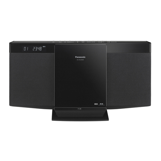
Product Color: (K)...Black Type
PAGE
Operations ------------------------------------------------- 13
5.2. Connections ----------------------------------------------- 14
5.3. Disc operations ------------------------------------------- 14
5.4. iPod or iPhone Operation ------------------------------ 15
6 Self Diagnostic and Doctor Mode Setting -------------- 16
6.1. Self Diagnostic Mode ----------------------------------- 16
6.2. Self Diagnostic Function Error Code ---------------- 17
6.3. Doctor Mode Table--------------------------------------- 18
6.4. Sales Demonstration Lock Function Mode -------- 24
7 Service Fixture & Tools --------------------------------------- 25
8 Disassembly and Assembly Instructions--------------- 26
8.1. Disassembly flow chart --------------------------------- 27
8.2. Types of Screws------------------------------------------ 28
8.3. Main Parts Location Diagram ------------------------- 28
8.4. Disassembly of Net Frame Assembly--------------- 29
8.5. Disassembly of Base Stand Assembly ------------- 31
© Panasonic Corporation 2011. All rights reserved.
Unauthorized copying and distribution is a violation of
law.
Compact Stereo System
SC-HC25GS
SC-HC25GT
SC-HC25PU
SC-HC25GSX
PSG1104005CE
PAGE
Advertisement
Table of Contents

Related Manuals for Panasonic SC-HC25GS


Summary of Contents for Panasonic SC-HC25GS
-
Page 1: Table Of Contents
4 Specifications ----------------------------------------------------12 8.4. Disassembly of Net Frame Assembly--------------- 29 5 Location of Controls and Components ------------------13 8.5. Disassembly of Base Stand Assembly ------------- 31 © Panasonic Corporation 2011. All rights reserved. Unauthorized copying and distribution is a violation of law. - Page 2 8.6. Disassembly of Docking Lid --------------------------- 31 15.10. PANEL, IR, DOOR SWITCH, BRIDGE & 8.7. Replacement of CD Door Ornament ---------------- 32 BUTTON CIRCUIT -------------------------------------105 15.11. SMPS CIRCUIT ----------------------------------------- 106 8.8. Replacement of CD Door Base----------------------- 34 8.9. Disassembly of Front Cabinet Assembly----------- 37 16 Printed Circuit Board----------------------------------------- 107 8.10.
-
Page 3: Safety Precautions
1 Safety Precautions 1.1. General Guidelines 1. When servicing, observe the original lead dress. If a short circuit is found, replace all parts which have been overheated or damaged by the short circuit. 2. After servicing, see to it that all the protective devices such as insulation barriers, insulation papers shields are properly installed. -
Page 4: Caution For Ac Cord (For Gs/Gsx Only)
1.2. Caution for AC Cord (For GS/GSX only) -
Page 5: Before Repair And Adjustment
1.3. Before Repair and Adjustment Disconnect AC power, discharge unit AC Capacitors as such C702, C710, C725, C727 and C728 through a 10W, 1W resistor to ground. Caution : DO NOT SHORT-CIRCUIT DIRECTLY (with a screwdriver blade, for instance), as this may destroy solid state devices. After repairs are completed, restore power gradually using a variac, to avoid overcurrent. -
Page 6: Safety Part Information
1.6. Safety Part Information Safety Parts List: There are special components used in this equipment which are important for safety. These parts are marked by in the Schematic Diagrams, Exploded View & Replacement Parts List. It is essential that these critical parts should be replaced with manufacturer’s specified parts to prevent shock, fire or other hazards. -
Page 7: Warning
2 Warning 2.1. Prevention of Electro Static Discharge (ESD) to Electrostatically Sensi- tive (ES) Devices Some semiconductor (solid state) devices can be damaged easily by static electricity. Such components commonly are called Elec- trostatically Sensitive (ES) Devices. Examples of typical ES devices are integrated circuits and some field-effect transistors and semiconductor “chip”... -
Page 8: Precaution Of Laser Diode
2.2. Precaution of Laser Diode CAUTION! THIS PRODUCT UTILIZES A LASER. USE OF CONTROLS OR ADJUSTMENTS OR PERFORMANCE OF PROCEDURES OTHER THAN THOSE SPECIFIED HEREIN MAY RESULT IN HAZARDOUS RADIATION EXPOSURE. Caution: This product utilizes a laser diode with the unit turned "on", invisible laser radiation is emitted from the pickup lens. Wavelength: 790 nm (CD) Maximum output radiation power from pickup: 100 μW/VDE Laser radiation from the pickup unit is safety level, but be sure the followings:... -
Page 9: Service Caution Based On Legal Restrictions
2.3. Service caution based on Legal restrictions 2.3.1. General description about Lead Free Solder (PbF) The lead free solder has been used in the mounting process of all electrical components on the printed circuit boards used for this equipment in considering the globally environmental conservation. The normal solder is the alloy of tin (Sn) and lead (Pb). -
Page 10: Handling Precaution For Traverse Deck
2.4. Handling Precaution for Traverse Deck The laser diode in the optical pickup unit may break down due to static electricity of clothes or human body. Special care must be taken avoid caution to electrostatic breakdown when servicing and handling the laser diode in the Traverse Deck. Cautions to Be Taken in Handling the Optical Pickup Unit 2.4.1. -
Page 11: Service Navigation
3 Service Navigation 3.1. Service Information This service manual contains technical information which will allow service personnel’s to understand and service this model. Please place orders using the parts list and not the drawing reference numbers. If the circuit is changed or modified, this information will be followed by supplement service manual to be filed with original service manual. -
Page 12: Specifications
4 Specifications Power consumption in standby mode: 0.2 W (approximate) (For GS/PU only) Power consumption in standby mode: 0.1 W (approximate) (For GT only) Amplifier Section • Specifications are subject to change without notice. Mass and RMS Output Power Stereo Mode dimensions are approximate. -
Page 13: Location Of Controls And Components
5 Location of Controls and Components 5.1. Main Unit & Remote Control Key Button Operations... -
Page 14: Connections
5.2. Connections 5.3. Disc operations... -
Page 15: Ipod Or Iphone Operation
5.4. iPod or iPhone Operation Compatibility iPod/iPhone • For compatibility of iPod/iPhone please refer to Operating Instructions... -
Page 16: Self Diagnostic And Doctor Mode Setting
6 Self Diagnostic and Doctor Mode Setting This unit is equipped with features of self diagnostic & doctor mode setting for checking the functions & reliability. 6.1. Self Diagnostic Mode Here is the procedures to enter into Self Diagnostic Mode. Step 1 : Turn on the unit. -
Page 17: Self Diagnostic Function Error Code
6.2. Self Diagnostic Function Error Code 6.2.1. CD Mechanism Error Code Table Error Code Diagnostic Contents Description of error Automatic FL Display Remarks CD H15 CD Open Abnormal During operation Press [ ] on main unit for POS_SW_R On fail to be next error. -
Page 18: Doctor Mode Table
6.3. Doctor Mode Table Here is the procedures to enter into Doctor Mode. Step 1 : Turn on the unit. Step 2 : Select CD mode. Step 3 : Pressing and hold [ ] on main unit then press [4] follow by [7] using the remote control. Step 4 : The display show as follow. - Page 19 6.3.2. Doctor Mode Table 2 Item Key Operation FL Display Mode Name Description Front Key FL Display Test To check the FL segments In Doctor Mode: display (All segments will Press [1] button on remote control. light up) To cancel, press [0] button on remote control.
- Page 20 6.3.3. Doctor Mode Table 3 Mode Name Description Front Key CD Self-Adjusment To display result of self In Doctor Mode: Display adjustment for CD. Press [ ] follow by [1] & then [4] button on remote control. To cancel, press [0] button on remote control.
- Page 21 6.3.4. Doctor Mode Table 4 Mode Name Description Front Key In Doctor Mode: Region Setting Check To check Region setting of Press [ ] follow by [1] & then [6] unit. button on remote control. Refer to 6.3.8 for the Region To cancel, press [0] button on remote Setting destination control.
- Page 22 6.3.6. CD Traverse Test (For CD) 6.3.7. CD Reliability Test (For CD)
- Page 23 6.3.8. Region Check Table (For Tuner) Region Model Series Country HC25 P/PC North America HC25 EG/EF Germany, France HC25 DBEB HC25 GT/GK/GS/PU S.E. Asia, Latin America HC25 Oceania 6.3.9. Model setting Region No. Function Model With iPod With Shock Proof HC25...
-
Page 24: Sales Demonstration Lock Function Mode
6.4. Sales Demonstration Lock Function Mode 6.4.1. Entering into sales Demo Mode Here is the procedures to enter into Sales Demonstration Lock. Step 1 : Turn on the unit. Step 2 : Select to any mode function, press and hold [ ] key and follow by [ ] key. -
Page 25: Service Fixture & Tools
7 Service Fixture & Tools Prepare service tools before process service position. Ref. No. Service Tools Remarks SFT1 Main P.C.B. (CN7002) - CD Servo P.C.B. (CN7002) RFKZHC55K1 (27P FFC) SFT3 Main P.C.B. (CN7902) - CD Servo P.C.B. (CN7901) RFKZHC35 (Extension P.C.B.) -
Page 26: Disassembly And Assembly Instructions
8 Disassembly and Assembly Instructions Caution Note: • This section describes the disassembly and/or assembly procedures for all major printed circuit boards & main compo- nents for the unit. (You may refer to the section of “Main components and P.C.B Locations” as described in the service manual) •... -
Page 27: Disassembly Flow Chart
8.1. Disassembly flow chart The following chart is the procedure for disassembling the casing and inside parts for internal inspection when carrying out the ser- vicing. To assemble the unit, reverse the steps shown in the chart below. -
Page 28: Types Of Screws
8.2. Types of Screws 8.3. Main Parts Location Diagram... -
Page 29: Disassembly Of Net Frame Assembly
8.4. Disassembly Frame Caution : During assembly of Net Frame Assembly (L), ensure it is fixed properly. Assembly 8.4.1. Disassembly of Net Frame Assem- bly (L) Step 1 : Gently lift up Net Frame Assembly (L) in order of sequences (1) to (4) to release 4 bosses as shown. Step 2 : Remove Net Frame Assembly (L) as arrow shown. - Page 30 8.4.2. Disassembly of Net Frame Assem- Caution : During assembly of Net Frame Assembly (R), ensure it is fixed properly. bly (R) Step 1 : Gently lift up Net Frame Assembly (R) in order of sequences (1) to (4) to release 4 bosses as shown. Step 2 : Remove Net Frame Assembly (R) as arrow shown.
-
Page 31: Disassembly Of Base Stand Assembly
8.5. Disassembly of Base Stand 8.6. Disassembly of Docking Lid Assembly Step 1 : Press to open the iPod Assembly. Step 1 : Remove 2 screws. Step 2 : Lift up the Base Stand Assembly. Step 2 : Push to remove Docking Lid as shown. -
Page 32: Replacement Of Cd Door Ornament
Caution : During assembly of Docking Lid, ensure it is fully 8.7. Replacement of CD Door Orna- insert into the slot. ment 8.7.1. Disassembly of CD Door Ornament Step 1 : Slide the CD Door to open it. Step 2 : Slightly push up the CD Door Ornament as arrow shown using a screwdriver to releasing both catches. - Page 33 Step 4 : Lift up to remove CD Door Ornament. 8.7.2. Assembly of CD Door Ornament Step 1 : Align the catch of CD Door Ornament onto the hole of CD Door Base. Step 2 : Push down the CD Door Ornament to Fix it. Step 3 : Push down the CD Door Ornament, a “click”...
-
Page 34: Replacement Of Cd Door Base
Step 4 : Slide the CD Door to close it. 8.8. Replacement of CD Door Base • Refer to “Disassembly of CD Door Ornament” 8.8.1. Disassembly of CD Door Base Step 1 : Slide the CD Door Base to close it. Step 2 : Remove 4 screws. - Page 35 Step 3 : Slightly lift up the CD Door Base. Step 5 : Push the CD Door Base upwards. Step 4 : Slide the CD Door Base towards to the left. Step 6 : Lift up and remove the CD Door Base.
- Page 36 8.8.2. Assembly of CD Door Base Step 3 : Align the CD Door Base onto the Slider Top and Slider Bottom as diagram shown. Step 1 : Place the CD Door Base onto Front Cabinet. Caution : Ensure that the 3 catch are inserted into the respective slots of CD Door Base.
-
Page 37: Disassembly Of Front Cabinet Assembly
8.9. Disassembly of Front Cabinet Step 3 : Slide the CD Door to open it. Assembly • Refer to “Disassembly of Net Frame Assembly” • Refer to “Disassembly of Base Stand Assembly” • Refer to “Disassembly of Docking Lid” Step 1 : Remove 8 screws in order of sequences (1) to (8) as shown. - Page 38 Step 6 : Remove 4 screws in order of sequences (1) to (4) as Step 8 : Detach 8P FFC at the connector (CN303) on Main shown. P.C.B.. Step 9 : Remove Front Cabinet Assembly. Step 7 : Lift up the Front Cabinet Assembly as arrow shown. Caution : During assembling, ensure 8P FFC dress on top of CD Mecha Rib.
-
Page 39: Disassembly Of Lcd Window
8.10. Disassembly of LCD Window Step 3 : Remove 6 screws in order of sequences (1) to (8) as shown. • Refer to “Disassembly of Net Frame Assembly” • Refer to “Disassembly of Base Stand Assembly” • Refer to “Disassembly of Docking Lid” •... - Page 40 Step 5 : Detach 8P FFC at the connector (CN303) on Main Step 7 : Release 10 catches in order of sequences (1) to (10). P.C.B.. Caution : Do not use strong force as it may damage the LCD Window. Step 6 : Remove Front Cabinet Assembly.
-
Page 41: Disassembly Of Gear Box Assembly
8.11. Disassembly Gear 8.11.1. Disassembly of Motor P.C.B. • Refer to “Disassembly of Gear Box Assembly” Assembly • Refer to “Disassembly of Net Frame Assembly” Step 1 : Release 2P wire from slot. • Refer to “Disassembly of Base Stand Assembly” Caution : During assembling, ensure the 2P wire is dress •... - Page 42 Step 4 : Desolder pin on the solder side of Motor P.C.B.. and 8.11.2. Disassembly of Belt, Pully Gear, remove the Motor P.C.B.. Middle Gear and Drive Gear. • Refer to “Disassembly of Gear Box Assembly” Step 1 : Remove Belt. Step 2 : Remove 1 screw.
- Page 43 Step 3 : Remove Pulley Gear. Step 6 : Use the minus screwdriver to release a catch as shown. Step 4 : Remove 1 screw. Step 7 : Remove Drive Gear. Step 5 : Remove Middle Gear.
-
Page 44: Replacement Of Rack Top & Slider Top
8.11.3. Disassembly of Motor Assembly 8.12. Replacement of Rack Top & • Refer to “Disassembly of Gear Box Assembly” Slider Top • Refer to (Step 1) to (Step 4) of item 8.11.1 • Refer to “Disassembly of Net Frame Assembly” •... - Page 45 Step 4 : Remove Slider Top. 8.12.2. Assembly of Rack Top & Slider Top Step 1 : Slide in the Slider Top. Step 2 : Fix Rack Top. Caution : During assembling, ensure the Rack Top is prop- erly seated onto guides, a “click” sound is heard when the Rack Top is fully catched.
-
Page 46: Disassembly Of Bridge P.c.b. & Door Switch P.c.b
Step 3 : Fix 2 screws. 8.13. Disassembly of Bridge P.C.B. & Door Switch P.C.B. • Refer to “Disassembly of Net Frame Assembly” • Refer to “Disassembly of Base Stand Assembly” • Refer to “Disassembly of Docking Lid” • Refer to “Disassembly of CD Door Ornament” •... - Page 47 Step 3 : Release the Wire from the slot. Caution : During assembling, ensure that the 3P cable is dressed into the slots as shown. Caution : During assembling, ensure that the 2P wire is Step 4 : Remove 1 screw. dressed into the slots as shown.
-
Page 48: Replacement Of Door Shaft & Slider Bottom
8.14. Replacement of Door Shaft & Step 3 : Upset the Front Cabinet Assembly. Step 4 : Remove Door Shaft. Slider Bottom Step 5 : Remove the Slider Bottom. • Refer to “Disassembly of Net Frame Assembly” • Refer to “Disassembly of Base Stand Assembly” •... - Page 49 8.14.2. Assembly of Door Shaft & Slider Step 2 : Slot in the one end of the Door Shaft into the hole as shown in the diagram above. Bottom Step 1 : Slot the Slider Bottom into the Door Shaft. Caution : During assembling, ensure Slider Bottom is turned downwards as diagram show.
-
Page 50: Replacement Of Timing Gear Shaft
Step 4 : Upset the Front Cabinet Assembly. 8.15. Replacement of Timing Gear Step 5 : Push the Door Shaft as arrow shown. Shaft Step 6 : Make sure that the Door Shaft is fixed by the Guide. • Refer to “Disassembly of Net Frame Assembly” •... -
Page 51: Disassembly Of Top Ornament Unit & Button P.c.b
8.15.2. Assembly of Timing Gear Shaft 8.16. Disassembly of Top Ornament Unit & Button P.C.B. Step 1 : Slot in the Timing Gear Shaft into the hole as shown. • Refer to “Disassembly of Net Frame Assembly” • Refer to “Disassembly of Base Stand Assembly” •... -
Page 52: Disassembly Of Ir P.c.b. & Panel P.c.b
8.16.2. Disassembly of Button P.C.B. 8.17. Disassembly of IR P.C.B. & • Refer to “Disassembly of Top Ornament Unit” Panel P.C.B. • Refer to “Disassembly of Net Frame Assembly” Step 1 : Remove 3 screws. • Refer to “Disassembly of Base Stand Assembly” •... - Page 53 Step 4 : Detach 9P FFC at the connector (CN900) on Main Caution : During assembling ensure that the 9P FFC & 3P Wire is fix into slots as shown and paste Conductive Cloth. P.C.B.. Step 5 : Lift up Conductive Cloth. Step 6 : Release the 9P FFC &...
-
Page 54: Disassembly Of Cd Mechanism
8.18. Disassembly of CD Mechanism Caution : During assembling of the CD Mechanism, ensure that the 27P FFC & 5P wire fold as picture shown to pre- • Refer to “Disassembly of Net Frame Assembly” vent track jump. • Refer to “Disassembly of Base Stand Assembly” •... -
Page 55: Disassembly Of Cd Servo P.c.b
8.19. Disassembly Servo Step 3 : Remove 3 screws. P.C.B. • Refer to “Disassembly of CD Mechanism” Step 1 : Release both catches and push down the fixed pin as arrow shown. Step 4 : Desolder pins on the solder side of CD Servo P.C.B.. Step 2 : Lift up the Mecha Chassis to remove Traverse Deck. -
Page 56: Disassembly Of Jack Lid
Step 7 : Attach short pin to Traverse Assembly. 8.20. Disassembly of Jack Lid Step 8 : Remove the CD Servo P.C.B.. • Refer to “Disassembly of Net Frame Assembly” • Refer to “Disassembly of Base Stand Assembly” • Refer to “Disassembly of Docking Lid” •... - Page 57 Step 3 : Push inward the shaft of the Jack Lid in the direction Caution : During assembling, ensure the Jack Lid is prop- erly slot into the hole of the Rear Cabinet Assembly. as shown. Step 4 : Remove Jack Lid in the direction as shown.
-
Page 58: Disassembly Of Tuner P.c.b
8.21. Disassembly of Tuner P.C.B. Caution : During assembling of the Tuner P.C.B., ensure that the iPod cable is fix into the slot and groove as shown. • Refer to “Disassembly of Net Frame Assembly” • Refer to “Disassembly of Base Stand Assembly” •... -
Page 59: Disassembly Of Smps P.c.b
8.22. Disassembly of SMPS P.C.B. Step 5 : Detach 6P wire at the connector (CN905) on SMPS P.C.B.. • Refer to “Disassembly of Net Frame Assembly” Step 6 : Remove SMPS Assembly. • Refer to “Disassembly of Base Stand Assembly” •... - Page 60 Step 8 : Lift up Himelon. Step 10 : Gently push up the SMPS Shield Plate to release the Caution : Replace the Himelons if they are torn during dis- catches. assembling. Step 11 : Remove SMPS Shield Plate. Step 9 : Gently push up the SMPS Shield Plate to release the catches.
-
Page 61: Replacement Of Diode (D702)
Caution: During assembling of SMPS P.C.B., ensure that 8.23. Replacement of Diode (D702) the SMPS P.C.B. is properly seated on the locators. • Refer to “Disassembly of SMPS P.C.B.” 8.23.1. Disassembly of Diode (D702) Caution : Handle the SMPS P.C.B. with care. Avoid touch- ing the heatsink due to high temperature after use. - Page 62 Step 3 : Remove the Diode (D702). 8.23.2. Assembly of Diode (D702) Step 1 : Apply grease to the heatsink unit. Step 2 : Fix the Diode (D702) onto SMPS P.C.B.. Step 3 : Fix the Diode (D702) onto the heatsink unit with 1 screws.
-
Page 63: Replacement Of Transistor (Q701)
8.24. Replacement Transistor Step 3 : Remove 1 screw. (Q701) • Refer to “Disassembly of SMPS P.C.B.” 8.24.1. Disassembly of Transistor (Q701) Caution : Handle the SMPS P.C.B. with care. Avoid touch- ing the heatsink due to high temperature after use. Step 1 : Desolder pins of the Transistor (Q701) on the solder side of SMPS P.C.B.. -
Page 64: Disassembly Of Docking Tub Unit
8.24.2. Assembly of Transistor (Q701) 8.25. Disassembly of Docking Tub Unit Step 1 : Apply grease to the heatsink unit. • Refer to “Disassembly of Net Frame Assembly” Step 2 : Fix the Transistor (Q701) onto SMPS P.C.B.. • Refer to “Disassembly of Base Stand Assembly” Step 3 : Fix the Transistor (Q701) onto the heatsink unit with 1 •... - Page 65 Step 3 : Release iPod Open Spring from the Docking Tub Unit Step 4 : Remove iPod Open Spring as arrow shown. hole as shown. Caution : Keep iPod Open Spring in the safe place and place them back during assembling. Step 5 : Release 2 catches.
- Page 66 Step 7 : Upset the Docking Tub Unit. 8.25.1. Disassembly of iPhone P.C.B. Step 8 : Release the shield wire from the slot. • Refer to “Disassembly of Docking Tub Unit” Caution : During assembling, ensure shield wire is fixed into the slot.
- Page 67 Caution : During assembling of Tub Cover, ensure it is Caution : During assembling, ensure that the iPhone P.C.B. fixed properly into the slot. is properly seated onto the 3 locators. Step 3 : Remove iPhone P.C.B..
-
Page 68: Disassembly Of Speaker Unit
8.25.2. Disassembly of Docking Cover 8.26. Disassembly of Speaker Unit • Refer to “Disassembly of Docking Tub Unit” • Refer to “Disassembly of Net Frame Assembly” • Refer to “Disassembly of Base Stand Assembly” Step 1 : Release 2 Guides. •... -
Page 69: Disassembly Of Main P.c.b
8.26.2. Disassembly of Woofer Speaker 8.27. Disassembly of Main P.C.B. (SP2) • Refer to “Disassembly of Net Frame Assembly” • Refer to “Disassembly of Base Stand Assembly” Step 1 : Detach 2P wire at the connector (CN106) on Main • Refer to “Disassembly of Docking Lid” P.C.B.. - Page 70 Step 4 : Detach 2P wire at the connector (CN106) on Main Caution : Ensure the Main P.C.B. unit is insert into the hole of Rear Cabinet Assembly as shown. Check Aux Jack P.C.B.. (JK951) & Headphone Jack (JK952). Step 5 : Detach 7P wire at the connector (CN901) on Main P.C.B..
-
Page 71: Service Position
9 Service Position Note: For description of the disassembly procedures, see the Section 8 9.1. Checking & Repairing of Panel Step 9 : Use a tape to keep the close switch (S643) depressed. P.C.B. Step 1 : Remove of Net Frame Assembly. Step 2 : Remove of Base Stand Assembly. -
Page 72: Checking & Repairing Of Cd Servo P.c.b
Step 11 : Connect 8P FFC at the connector (CN303) on Main 9.2. Checking & Repairing of CD P.C.B.. Servo P.C.B. Note : Insert CD before Checking CD Servo P.C.B. Step 1 : Remove of Net Frame Assembly. Step 2 : Remove of Base Stand Assembly. Step 3 : Remove of Docking Lid. - Page 73 Step 9 : Place the CD Mechanism on the Insulating Material. Step 14 : Use a tape to keep the close switch (S643) depressed. Step 10 : Place the Extension P.C.B. (RFKZHC35) on the Insu- lating Material. Step 11 : Connect 5P cable from Main P.C.B. to Extension P.C.B..
-
Page 74: Checking & Repairing Of Main (Side B) P.c.b
9.3. Checking & Repairing of Main 9.4. Checking & Repairing of Main (Side B) P.C.B. (Side A) P.C.B. • Refer to (Step 1) - (Step 16) of item 9.2 Step 1 : Remove of Net Frame Assembly. Step 1 : Check and repair Main (Side B) P.C.B. according to the Step 2 : Remove of Base Stand Assembly. - Page 75 Step 10 : Detach 6P wire at the connector (CN905) on SMPS Step 13 : Remove 1 screw. P.C.B.. Step 14 : Release Speaker Wire from the slot. Step 11 : Remove SMPS Assembly. Step 15 : Release 2 catches. Step 12 : Lift up Conductive Cloth.
- Page 76 Step 17 : Place the Main P.C.B. on the Insulating Material as Step 22 : Connect 27P extension cable (RFKZHC55K1) from shown. CN7002 on the Main P.C.B. to CN7002 on the CD Servo P.C.B.. Step 18 : Place the CD Mechanism on the Insulating Material. Step 23 : Use a tape to keep the close switch (S643) Step 19 : Place the Extension P.C.B.
- Page 77 Step 24 : Connect 8P FFC at the connector (CN303) on Main Step 26 : Check & repair Main P.C.B. (Side A) according to the P.C.B.. diagram shown. Step 25 : Connect 6P wire at the connector (CN905) on SMPS P.C.B..
-
Page 78: Checking & Repairing Of Smps P.c.b
9.5. Checking & Repairing of SMPS Step 3 : Gently push up the SMPS Shield Plate to release the catches. P.C.B. • Refer to (Step 1) - (Step 11) of item 9.4 Step 1 : Lift up Himelons. Caution : Replace the Himelons if they are torn during dis- assembling. - Page 79 Step 5 : Remove SMPS Shield Plate. Step 7 : Place the Support Block to support the Front Cabinet Assembly as shown. Step 8 : Connect 8P FFC at the connector (CN303) on Main P.C.B.. Step 6 : Use a tape to keep the close switch (S643) depressed. Step 9 : Connect 6P wire at the connector (CN905) on SMPS P.C.B..
-
Page 80: Voltage Measurement & Waveform Chart
IC7704 REF NO. MODE CD PLAY IC7704 REF NO. MODE CD PLAY IC7704 REF NO. MODE CD PLAY IC7501 REF NO. MODE CD PLAY IC7851 REF NO. MODE CD PLAY Q7601 REF NO. MODE CD PLAY SC-HC25GS/GSX/GT/PU CD SERVO P.C.B. -
Page 81: Main P.c.b. (1/3)
POWER ON STANDBY IC801 REF NO. MODE POWER ON STANDBY IC801 REF NO. MODE POWER ON STANDBY IC803 REF NO. MODE POWER ON STANDBY IC1000 REF NO. MODE POWER ON 11.7 17.1 10.0 STANDBY 11.7 17.1 10.0 SC-HC25GS/GSX/GT/PU MAIN P.C.B. -
Page 82: Main P.c.b. (2/3)
POWER ON STANDBY Q7902 Q7903 QR100 QR801 QR1000 REF NO. MODE POWER ON STANDBY QR2000 QR2001 QR7900 REF NO. MODE POWER ON STANDBY IC102 REF NO. MODE CD PLAY STANDBY IC700 REF NO. MODE CD PLAY STANDBY SC-HC25GS/GSX/GT/PU MAIN P.C.B. -
Page 83: Main P.c.b. (3/3)
STANDBY REF NO. IC2003 MODE CD PLAY STANDBY Q950 Q951 Q952 REF NO. MODE CD PLAY STANDBY SC-HC25GS/GSX/GT/PU MAIN P.C.B. 10.5. PANEL P.C.B. IC900 REF NO. MODE POWER ON STANDBY IC900 REF NO. MODE POWER ON STANDBY REF NO. IC900... -
Page 84: Tuner P.c.b
10.7. TUNER P.C.B. IC52 REF NO. MODE TUNER SC-HC25GS/GSX/GT/PU TUNER P.C.B. 10.8. Waveform Chart 0.1Vp-p(200usec/div) 3.8Vp-p(50nsec/div) 3Vp-p(50nsec/div) 1.1Vp-p(10usec/div) 2.1Vp-p(10usec/div) 1.4Vp-p(5usec/div) 2.8Vp-p(5usec/div) 1.2Vp-p(200usec/div) 1.5Vp-p(200usec/div) -
Page 85: Illustration Of Ic's, Transistors And Diodes
11 Illustration of IC’s, Transistors and Diodes C0JBAR000587 (16P) C0HBA0000295 (44P) C0CBCDC00052 C0GBY0000117 (30P) C0DBEYY00123 (8P) C0JBAU000036 (14P) MFI341S2164 (20P) C0DBAYY01077 (8P) C3ABMY000027 (50P) MN6627947RB (144P) C0DBAYY00462 (8P) RFKWMHC25M0 (100P) C3EBFC000042 (8P) C0DBGYY00887 (4P) C0JBAR000586 (14P) C0DBZMC00006 (4P) C0DBZYY00448 (8P) C0FBAK000026 (16P) No.1 C0JBAE000438 (14P) -
Page 87: Overall Simplified Block
12 Overall Simplified Block 12.1. Voltage / Current / Ground Diagram DSP / D Amp 0.03A BT LED Main LC filter SMPS CD Motor 0.120A iPod MOTOR DRIVER CD_USB Regulator+3.3V CD + CPIC FL Driver TUNER MCU SYS 3.3V Regulator+3.3V Remote IR Vp / FL LCD Display... -
Page 88: Control & Signal Diagram
12.2. Control & Signal Diagram IC2000 Invertor +3.3V Buffering Servo Processing +3.3V ASP IC μP+LSI IC103 Right Speaker MCLK MCLK LRCK LRCK BCLK BCLK DATA EEPROM DATA Left Speaker iPod (D) IC700 IC102 Multiplexor iPhone/iPod 0X/0Y M.PORT/AUX 1X/1Y MCLK 2X/2Y IC2003 LRCK 3X/3Y... -
Page 89: Block Diagram
CN7002 CN7002 CN303 CN901 P903* P904 VOTR+ CN7002 CN7002 CN303 CN901 P903* P904 VOTR- MOTOR P.C.B. CN7002 CN7002 LDSW LDSW 3.3V Q7001 SWITCH BRIDGE P.C.B. NOTE: “ * ” REF IS FOR INDICATION ONLY SC-HC25GS/GSX/GT/PU SERVO & SYSTEM CONTROL BLOCK DIAGRAM... -
Page 90: Ic Terminal Chart
DQ2 / DQ13 5 / 46 DQ3 / DQ12 6 / 45 DQ4 / DQ11 8 / 43 DQ5 / DQ10 9 / 42 DQ6 / DQ9 11 / 40 DQ7 / DQ8 12 / 39 SC-HC25GS/GSX/GT/PU IC TERMINAL CHART... -
Page 91: Audio Block Diagram
D-AMP RESET RSTX 45 D-AMP RESET MPORT R 5 1Y PDET2 PDET2 ERROR 17 (EXT-IN) MPORT L 14 1X TEST1 7 MUX A FROM MUX A 10 A SERVO & SYSTEM CONTROL MUX B MUX B SC-HC25GS/GSX/GT/PU AUDIO BLOCK DIAGRAM... -
Page 92: Power Supply (1/2) Block Diagram
PDET1 IC1005 C0DBGYY00887 +3.3V REGULATOR 4 VIN STBY3R3V STBY3R3V 3.3V VOUT 3 1 CE IC803 C0EBE0000434 RESET NRST STBY3R3V STBY3R3V NRST 1 OUT IN 2 NOTE: “ * ” REF IS FOR INDICATION ONLY SC-HC25GS/GSX/GT/PU POWER SUPPLY (1/2) BLOCK DIAGRAM... -
Page 93: Power Supply (2/2) Block Diagram
TO POWER SUPPLY BLOCK (1/2) CN900 CN900 7.5V 7.5V 7.5V CN900 CN900 D3R3V D3.3V D3.3V 3.3V IR P.C.B. STBY3R3V STBY3R3V CN900 CN900 P902B* P902A* STDBY3.3V 3.3V NOTE: “ * ” REF IS FOR INDICATION ONLY SC-HC25GS/GSX/GT/PU POWER SUPPLY (2/2) BLOCK DIAGRAM... -
Page 94: Wiring Connection Diagram
14 Wiring Connection Diagram BUTTON P.C.B. SOLDER SIDE CAUTION RISK OF ELECTRIC SHOCK AC VOLTAGE LINE. 6 ..2 CN6802 7 ..1 PLEASE DO NOT TOUCH THIS P.C.B. TO OPTICAL PICKUP UNIT (FOR DEBUG) CN905 1 . -
Page 95: Schematic Diagram
15 Schematic Diagram 15.1. Schematic Diagram Notes • Voltage and signal line (All schematic diagrams may be modified at any time with : +B Signal Line the development of new technology) : CD Audio Input Signal Line Notes: S641: OPEN switch. : Audio Output Signal Line S643: CLOSE switch. -
Page 97: Cd Servo Circuit (1/2)
B1ADCF000001 C7152 R7208 C7230 0.01 LASER DRIVE R7151 K7101 R7220 C7239 X7205 C7267 R7221 C7205 C7206 D7650 C7225 X7201 B0BC5R6A0266 CD_IIS_MCLK 1000P C7226 DGND LDSW 1000P DGND1 SC-HC25GS/GSX/GT/PU NOTE: “ * ” REF IS FOR INDICATION ONLY CD SERVO CIRCUIT... -
Page 98: Cd Servo Circuit (2/2)
R7896 CN7901 3.3V USB_SEL IPOD_DET LID_RIGHT MAIN (USB/iPod) VBUS LDSW LID_LEFT CIRCUIT LID_RIGHT (CN7902*) IN SCHEMATIC LID_LEFT DGND VTUNER_IN DIAGRAM - 7 C7207 DVSS R7901 VTUNER USBDM K7268 USBDP R7903 R7902 3.3V R7904 33 DGND DGND1 SC-HC25GS/GSX/GT/PU CD SERVO CIRCUIT... -
Page 99: Main Circuit (1/4)
100K IPOD5V MULTIPLEXER IPOD5V IPOD_PCONT R707 100K IPOD_PCONT DGND DGND IC701 PW_VBUS ON/OFF R709 100K PW_VBUS C0CBCDC00052 IPOD_DET IPOD_DET +5V REGULATOR C703 C704 R711 C710 MU: MAIN (USB/iPod) SCHEMATIC DIAGRAM 3,7 C705 C706 TO MAIN CIRCUIT (3/4) SC-HC25GS/GSX/GT/PU MAIN CIRCUIT... -
Page 100: Main Circuit (2/4)
3.3V Q950 R968 TU_SDA R970 IN SCHEMATIC SDIO R967 CLK_TU_SCL DIAGRAM - 8 SCLK TU_RST R971 R966 TU_INT R969 R972 Q950 Q951 Q952 TO MAIN B1ADCE000012 B1GFGCAA0001 B1GFGCAA0001 CIRCUIT (4/4) MUTING CONTROL (HP) MUTING SWITCH MUTING SWITCH SC-HC25GS/GSX/GT/PU MAIN CIRCUIT... -
Page 101: Main Circuit (3/4)
100P R981 D3R3V D3.3V 100K FL_DI R832 LCD_DI 100K CLK_FL LCD_WR PANEL CIRCUIT FL_CE LCD_CE (CN900) R847 7.5V IN SCHEMATIC R820 100K 100K DIMMER DIAGRAM - 9 IC803 REM_IN C0EBE0000434 STANBY 3.3V RESET STBY3R3V C828 10V33 DGND SC-HC25GS/GSX/GT/PU MAIN CIRCUIT... -
Page 102: Main Circuit (4/4)
IC1009 CD RESET / RST REST_SW C0DBAYY01077 REST SW CD_LOADING DC/DC CONVERTER LOADING K1010 R7003 OPEN_SW DGND 3.3K 9V_GND PGND VCC18V R1124 R1123 R1126 Q7001 MAINV_DET B1ADCE000012 SWITCH NOTE: “ * ” REF IS FOR INDICATION ONLY SC-HC25GS/GSX/GT/PU MAIN CIRCUIT... -
Page 103: Main (Usb/Ipod) Circuit
R7915 Q7900 QR7900 B1GBCFJN0038 IPOD_PCONT POWER CONTROL R7902 DGND 4.7K PW_VBUS IPOD_DET Q7900 Q7903 Q7901 B1ADCF000001 B1ADCF000001 B1ABCF000176 SWITCH SWITCH SWITCH MU: MAIN (USB/iPod) SCHEMATIC DIAGRAM 3,7 NOTE: “ * ” REF IS FOR INDICATION ONLY SC-HC25GS/GSX/GT/PU MAIN (USB/iPod) CIRCUIT... -
Page 104: Iphone, Tuner & Motor Circuit
IN SCHEMATIC DIAGRAM - 4 SCLK CK52 G2A380Y00002 CK53 CK69 JK52 0.47 AM ANT AM ANT AM ANT 4.7K 4.7K CK65 CK66 CK67 CK68 CK54 NOTE: “ * ” REF IS FOR INDICATION ONLY SC-HC25GS/GSX/GT/PU iPhone / TUNER / MOTOR CIRCUIT... -
Page 105: Panel, Ir, Door Switch, Bridge & Button Circuit
S915 IN SCHEMATIC D3.3V REV SKIP FWD SKIP VOL - VOL + CD OPEN/CLOSE DIAGRAM - 5 7.5V DIMMER SC-HC25GS/GSX/GT/PU PANEL / IR / DOOR SWITCH / BRIDGE / BUTTON CIRCUIT NOTE: “ * ” REF IS FOR INDICATION ONLY... -
Page 106: Smps Circuit
150K R747 VINS ISENSE IC701 TH702 D4CC11040013 C732 R720 C0DBZMC00006 PROT DRIVER SHUNT REGULATOR R749 R728 C722 CTRL 1.5K C711 R727 2.2K OPTMR D715 C713 B0BC02900004 50V4.7 ZJ702 NOTE: “ * ” REF IS FOR INDICATION ONLY SC-HC25GS/GSX/GT/PU SMPS CIRCUIT... -
Page 107: Printed Circuit Board
C7315 C7704 R7331 C7339 C7338 D7342 R7336 K7705 TP36 R7322 TP39 C7626 C7233 C7334 IC7002 TP37 M7301* (SPINDLE MOTOR) 0707A-1 0707A-1 0707A-1 0707A-1 (SIDE A) (SIDE B) SC-HC25GS/GSX/GT/PU NOTE: " * " REF IS FOR INDICATION ONLY CD SERVO P.C.B. -
Page 108: Main P.c.b. (Side A)
IC702 TL818 TL824 R830 R892 C1106 K110 IC1005 QR801 R952 CK10 C959 R951 C162 R905 C958 C954 R955 R973 R953 L950 C953 R963 L954 C956 L955 R907 C952 R908 CL950 C957 R958 C993 0724AA-1 0724AA-1 (SIDE A) SC-HC25GS/GSX/GT/PU MAIN P.C.B. -
Page 109: Main P.c.b. (Side B)
CN900 Q950 TO RIGHT SPEAKER C160 R969 R966 JK952 JK951 JK1111 C961 Q952 CN106 CK12 Q951 C955 0724AA-1 0724AA-1 TO LEFT SPEAKER (SIDE B) SC-HC25GS/GSX/GT/PU NOTE: " * " REF IS FOR INDICATION ONLY HEADPHONE USB PORT MAIN P.C.B. (EXT-IN) -
Page 110: Iphone, Tuner & Motor P.c.b
C1302 MOTOR P.C.B. (REPX0915QF) 0724AB-1 0724AB-1 L1002 CK1300 2 3 4 0724AF-1 0724AF-1 P904 CN1002 MOTOR* 0724AF-1 0724AF-1 (SIDE B) (SIDE A) (SIDE B) SC-HC25GS/GSX/GT/PU NOTE: " * " REF IS FOR INDICATION ONLY iPhone / TUNER / MOTOR P.C.B. -
Page 111: Panel, Ir, Door Switch, Bridge & Button P.c.b
(REV SKIP) (FWD SKIP) (VOL -) (VOL +) (CD OPEN/CLOSE) R934 0751AB-1 0751AB-1 DOOR SWITCH P.C.B. (REPX0913AC) S643 P905B* (CLOSE) S641 (OPEN) 0751AC-1 0751AC-1 SC-HC25GS/GSX/GT/PU NOTE: " * " REF IS FOR INDICATION ONLY PANEL/ IR/ DOOR SWITCH/ BRIDGE/ BUTTON P.C.B. -
Page 112: Smps P.c.b
16.6. SMPS P.C.B. SMPS P.C.B. (REPX0917J) ZA700* D701 ZJ701 HEATSINK C710 TH701 Q701 R718 ZJ702 C702 TH702 R726 R748 R704 R703 C731 C728 R720 (MAIN TRANSFORMER) C705 R724 R728 D707 C703 PC702 C727 R745 L702 R747 R749 IC701 R719 C732 C722 R706 PC701... -
Page 113: Terminal Function Of Ic's
17 Terminal Function of IC’s 17.1. IC801 (RFKWMHC25M0) MICRO PROCESSOR IC Pin No. Mark Function No connection Pin No. Mark Function No connection No connection EE_CS EEPROM Chip Select No connection EE_SCL EEPROM Serial Clock APD_IN Auto Power Down Detect EE_SDA I/O EEPROM Serial Data (Active=High) -
Page 115: Exploded View And Replacement Parts List
18 Exploded View and Replacement Parts List 18.1. Exploded View and Mechanical replacement Parts List 18.1.1. Cabinet Parts Location P905B* (DOOR SWITCH P.C.B.) (MOTOR P.C.B.) P904 CN901 P903B* P905A* (BRIDGE P.C.B.) SC-HC25GS/GSX/GT/PU-K NOTE: " * " REF IS FOR INDICATION ONLY. CABINET DRAWINGS... - Page 116 ZJ1000 CN7002 CN303 ZJ702 CN905 CN7801 *HEATSINK (CD SERVO P.C.B.) ZJ701 CN7001 S7201 T701 CN7901 (SMPS P.C.B.) P751 CN7002 CN1002 CN1001 (iPhone P.C.B.) SC-HC25GS/GXS/GT/PU-K NOTE: " * " PART IS NOT SUPPLIED / REF IS FOR INDICATION ONLY. CABINET DRAWINGS...
- Page 117 FM INDOOR ANTENNA (FOR GT ONLY) AC CORD AM LOOP ANTENNA (FOR PU ONLY) AC CORD (FOR GS/GSX ONLY) AC PLUG ADAPTOR AC CORD (FOR PU ONLY) (FOR GS/GSX ONLY) SC-HC25GS/GSX/GT/PU F R O POLYFOAM (LEFT) POLYFOAM (RIGHT) SC-HC25GS/GSX/GT/PU-K PACKAGING DRAWINGS...
- Page 119 18.1.3. Mechanical Replacement Parts List Safety Ref. No. Part No. Part Name & Qty Remarks Description Safety Ref. No. Part No. Part Name & Qty Remarks REXX1185 3P CABLE WIRE Description (REMOTE SENSOR- PANEL) CABINET AND RGKX1062B-K1 DOOR ORNAMENT CHASSIS RYPX1117-S1 TOP ORNAMENT UNIT...
- Page 120 Safety Ref. No. Part No. Part Name & Qty Remarks Safety Ref. No. Part No. Part Name & Qty Remarks Description Description RMNX1012A-W1 LCD HOLDER COVER 1 K2CZ3YY00005 AC CORD GS/GSX RMNX1052-1 SMPS INSULATOR A 1 RQTX1251-M O/I BOOK (Sp) RMNX1053-1 SMPS INSULATOR B 1 RQTX1255-G...
-
Page 121: Electrical Replacement Parts List
18.2. Electrical Replacement Parts List Safety Ref. No. Part No. Part Name & Qty Remarks Description Safety Ref. No. Part No. Part Name & Qty Remarks IC2002 C0JBAU000036 Description IC2003 C0JBAE000438 IC7001 MN6627947RB PRINTED CIRCUIT IC7002 C0GBY0000117 BOARD IC7501 MFI341S2164 IC7704 C3ABMY000027 PCB1... - Page 122 Safety Ref. No. Part No. Part Name & Qty Remarks Safety Ref. No. Part No. Part Name & Qty Remarks Description Description D715 B0BC02900004 DIODE G2A380Y00002 INDUCTOR D717 B0JCME000035 DIODE L102 G1C150M00023 INDUCTOR D857 B0ACCK000012 DIODE L103 G1C150M00023 INDUCTOR D858 B0ACCK000012 DIODE L104...
- Page 123 Safety Ref. No. Part No. Part Name & Qty Remarks Safety Ref. No. Part No. Part Name & Qty Remarks Description Description X802 H2B800400007 CRYSTAL OSCILLA- W910 D0GBR00JA008 1/16W W911 D0GBR00JA008 1/16W X2000 H0J122200002 CRYSTAL OSCILLA- W912 D0GBR00JA008 1/16W X7201 H2D169500017 CRYSTAL OSCILLA- RESISTORS...
- Page 124 Safety Ref. No. Part No. Part Name & Qty Remarks Safety Ref. No. Part No. Part Name & Qty Remarks Description Description R748 D0GD335JA017 3.3M 1/8W R911 D0GB122JA008 1.2K 1/16W R749 D0GB103JA008 1/16W R912 D0GB152JA008 1.5K 1/16W R801 D0GBR00JA008 1/16W R913 D0GB222JA008 2.2K...
- Page 125 Safety Ref. No. Part No. Part Name & Qty Remarks Safety Ref. No. Part No. Part Name & Qty Remarks Description Description R7003 D0GB332JA008 3.3K 1/16W R7915 D0GB103JA008 1/16W R7004 D0GB102JA008 1/16W R7005 D0GB102JA008 1/16W CAPACITORS R7006 D0GBR00JA008 1/16W R7007 D0GBR00JA008 1/16W F1H1H102A885...
- Page 126 Safety Ref. No. Part No. Part Name & Qty Remarks Safety Ref. No. Part No. Part Name & Qty Remarks Description Description C715 F1H1H102A219 1000pF C1136 F2A1A1010024 100uF C716 F1H1C224A074 0.22uF C1302 F1G1C104A077 0.1uF C717 F1H1C154A002 0.15uF C1303 F1G1C104A077 0.1uF C718 F1H1E224A068 0.22uF...
- Page 127 Safety Ref. No. Part No. Part Name & Qty Remarks Description C7502 F1H1H103A885 0.01uF C7601 F1J1A106A041 10uF C7613 F1G1A1040006 0.1uF C7615 F1J1A106A041 10uF C7616 F1J1A106A041 10uF C7626 F1J1A106A041 10uF C7670 F1H1H103A885 0.01uF C7704 F1H1H150A971 15pF C7741 F1H1H103A885 0.01uF C7752 F1H1H103A885 0.01uF C7753 F1J1A106A041...
Need help?
Do you have a question about the SC-HC25GS and is the answer not in the manual?
Questions and answers