Table of Contents
Advertisement
Quick Links
INSTALLATION AND MAINTENANCE
INSTRUCTIONS
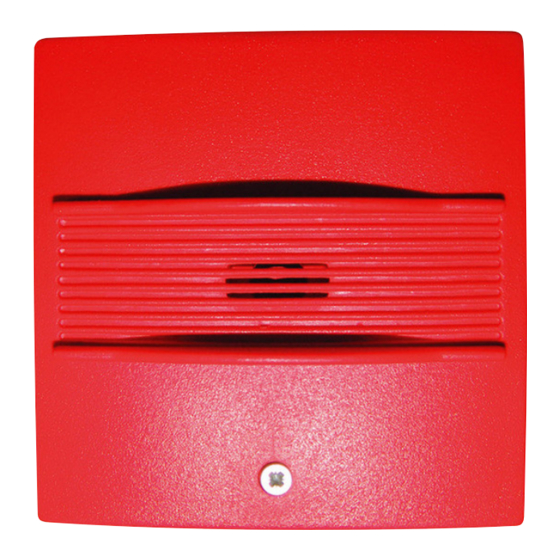
313-0021(RED) 313-0022(WHITE) TWINFLEX SOUNDPOINT
http://www.fike.co.uk/
General Description
resource-downloads/twinflex/
The Twinflex Soundpoint unit allows for audible indication when the system enters an alarm
condition. This device is compatible with the Twinflex 2-wire range of Fire Alarm equipment
and comprises a 2-wire zone-powered sounder. This device may be installed on the same
zone as the Multipoint detector/sounder and associated Twinflex devices.
Before Installation
The MCP must be installed in compliance with the control panel installation manual.
The installation must also meet the requirements of any local authority.
Spacing
Fike recommends spacing of call points in accordance with any local authority.
Device Installation
Surface Mounting
Fix the surface back box to a flat vertical surface using at least two of the four mounting
holes provided. The back box may be drilled to allow cable access as required. A
20mm hole is already provided at the rear. Zone cabling may be connected to the
terminals in the back box.
Flush Mounting
The Soundpoint may be flush mounted utilising the optional adaptor plate, combined
with any standard single gang flush mounting back box (with a minimum internal depth
of 47mm).
After installing the back box securely, attach the adaptor plate using the two screws
provided, and terminate your cables directly into a flying terminal block.
Installation 2nd Fix
Once all testing has been carried out on the cabling and 'continuity & integrity' has
been proven, the Soundpoint front may be installed.
Connect the wires from the Soundpoint front in to the appropriate terminals in the
back box according to the wire colours. The Soundpoint front may then be installed by
locating the upper mounting hooks into the back box and then pushing the unit gently
home. The single fixing screw may then be tightened as required.
Please remember that all high voltage testing must be carried out before the installation
of the Soundpoint front unit, otherwise the electronics will be damaged.
Document No. 26-0510 Issue 9
This document is only intended to be a guideline and is not applicable to all
situations. Information subject to full disclaimer at www.fike.com/disclaimer
Subject to change
Advertisement
Table of Contents

Subscribe to Our Youtube Channel
Related Manuals for Fike TWINFLEX 313-0021


Summary of Contents for Fike TWINFLEX 313-0021
- Page 1 The MCP must be installed in compliance with the control panel installation manual. The installation must also meet the requirements of any local authority. Spacing Fike recommends spacing of call points in accordance with any local authority. Device Installation Surface Mounting Fix the surface back box to a flat vertical surface using at least two of the four mounting holes provided.
- Page 2 Connections YELLOW BLUE Twinflex Soundpoints can be mixed on the same zone as other types of Twinflex device (eg. Twinflex Multipoint Detectors). The above diagram shows how to make the zone positive, zone negative and screen connections between the control panel and Twinflex Soundpoints. Refer to the instruction leaflets supplied with other Twinflex devices for their equivalent wiring/terminal labelling details.
- Page 3 Intended for use in the fire detection and fire alarm Systems in and around buildings ensure that the contents of this document are correct at time of publication, Fike shall be under no liability Essential characteristics Performance whatsoever in respect of such contents. E&OE...
Need help?
Do you have a question about the TWINFLEX 313-0021 and is the answer not in the manual?
Questions and answers