Table of Contents
Advertisement
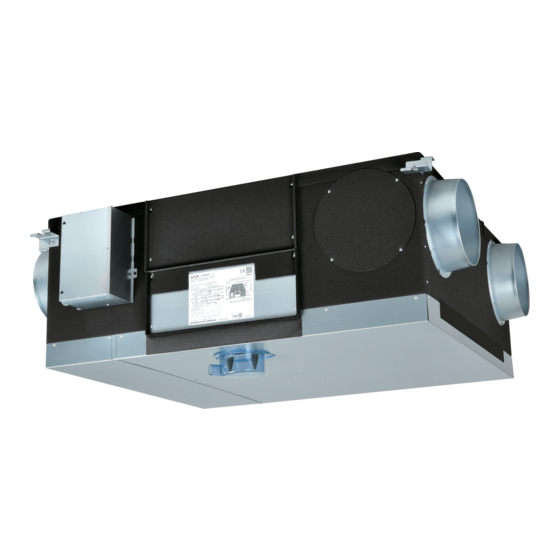
Lossnay Heat Recovery Ventilator
MODELS:
LGH-50RVS-E
LGH-80RVS-E
LGH-100RVS-E
Installation Instructions
This product needs to be installed properly in order to ensure
maximum functionality as well as safety.
Please be sure to read this installation manual before starting the
installation.
l Installation must be performed by a dealer or installation contractor.
Please note that improper installation may cause malfunction or
accident.
"Operating Instructions" and this manual must be handed over to
the customer after completing the installation.
For use by dealer/contractor
Contents
1. Safety precautions ...........................................2
2. Outline drawings ..............................................5
3. Standard installation examples........................6
4. Installation method ..........................................7
4.1 Hanging the Lossnay unit...........................7
4.2 Duct works .................................................8
4.3 Drain pipe work ..........................................9
4.4 Electrical installation.................................10
5. Function settings ...........................................17
6. Check points after installation work ...............29
7. Trial operation................................................30
Eng-1
2105876H63801
Advertisement
Table of Contents

Related Manuals for Mitsubishi Electric LGH-50RVS-E


Summary of Contents for Mitsubishi Electric LGH-50RVS-E
-
Page 1: Table Of Contents
2105876H63801 Lossnay Heat Recovery Ventilator MODELS: LGH-50RVS-E LGH-80RVS-E LGH-100RVS-E Installation Instructions For use by dealer/contractor This product needs to be installed properly in order to ensure Contents maximum functionality as well as safety. Please be sure to read this installation manual before starting the 1. -
Page 2: Safety Precautions
1. Safety precautions The following signs indicate that death or serious injury may be caused by failure to heed the precautions described below. WARNING Incorrect handling could cause serious injury or death. Do not modify or disassemble. It could cause fire, electric shock or injury. Do not disassemble The Lossnay unit and remote controller should not be installed where it is highly humid, like a bathroom, or other wet place. - Page 3 CAUTION Incorrect handling could cause injury or damage to property or household effects. Do not place a burning appliance in a place where it is exposed directly to the air from the Lossnay unit. It could cause an accident as a result of incomplete combustion. Do not use at a place where it is exposed to high temperatures (40˚C or higher), naked flames, or in environment with combustible fumes.
- Page 4 CAUTION Incorrect handling could cause injury or damage to property or household effects. In cold weather areas, even if they are within the range of operating conditions, dewing or freezing could occur on the main unit, where the duct is connected, or other sections, depending on the conditions of outdoor air and indoor temperature and moisture.
-
Page 5: Outline Drawings
Unit (mm) Ceiling suspension Dimensions Duct connecting flange Duct pitch Weight Weight with Nominal fixture pitch Model diameter (kg) maximum drain water LGH-50RVS-E 1001 LGH-80RVS-E 1185 1179 1051 LGH-100RVS-E 1185 1224 1179 1279 Accessory parts Screws x16 Duct connecting flanges... -
Page 6: Standard Installation Examples
3. Standard installation examples • Duct length Return air grille Model Distance (not Included) LGH-50RVS-E 1 m or more LGH-80 and 100RVS-E 2.5 m or more (exhaust air outlet) Lossnay unit (exhaust air outlet) (outside air intake) Electrically operated damper... -
Page 7: Installation Method
4. Installation method 4.1 Hanging the Lossnay unit 4.1.3 Preparing the anchor bolts Mount the washers (outer diameter of >21 mm for M10, >24 mm for 4.1.1 Attaching the duct connecting flanges M12) and nuts onto the pre-recessed anchor bolts (M10 or M12), as Use the supplied screws (size:4x8) to secure the duct connecting shown in the figure below. -
Page 8: Duct Works
4.2 Duct works 4.2.2 When changing the direction of the out door side duct (EA/OA) 4.2.1 Connecting the ducts (1) Removal of the flange cover (1) Fasten the duct securely to the duct connecting flange, and wrap Unscrew the flange cover mounting screws (4 pcs), and remove aluminium tape (field supply) around the joints so that there is no the flange cover. -
Page 9: Drain Pipe Work
4.3 Drain pipe work CAUTION • When installing the drain pipes, make sure there are no 1. Remove the installation label from the product, and prepare it for solvents or oils on the backflow stopper and drain pan. drain pipe installation. •... -
Page 10: Electrical Installation
* Be sure to install an all pole electric leakage isolator. * Always use an isolator for the main switch power connection. * Select proper circuit breaker according to the electrical current information in the chart below. Model LGH-50RVS-E LGH-80RVS-E LGH-100RVS-E Maximum current when operating [A]... - Page 11 TM1 terminal block using the round terminals. (level signal) Secure the cable with the bush. 9 When connecting to the City Multi or Mitsubishi Electric Air- (* Use an item that can firmly secure the cable such as a cable Conditioner Network System (MELANS) gland.)
- Page 12 When the external device has an Volt-free contact signal When interlocked with indoor unit of air conditioner or other external device including other manufactures • If the input is pulse signal, move the pulse input switch [SW2-2] to the ON position. (Refer to function settings No.
- Page 13 Note • Do not directly supply power from the Lossnay unit to the duct heater. Doing so could cause fire. • When connecting multiple cables to the terminal, use round • Install a circuit breaker for the duct heater in compliance with terminal.
- Page 14 When connecting to the City Multi, Mitsubishi Electric Air- When switching By-pass externally. Conditioner Network System (MELANS) Establish the wire connection by inserting the optional remote Shielded wire controller adapter (PAC-SA88HA-E) in the connector CN26 (White). Remote controller adapter Lossnay...
- Page 15 To start/stop Lossnay stand-alone operation without using the remote control Isolator Lossnay external control input Switch Start/stop the unit by a switch connected to TM2 Y Z . When turned the unit ON, it operates at fan speed 4 and automatic ventilation mode.
- Page 16 Control via Wi-Fi interface or MELCOBEMS MINI Connect the lead wire of a Wi-Fi interface or MELCOBEMS MINI to CN105 on circuit board of Lossnay unit. Regarding the model name of the connectable Wi-Fi interface or MELCOBEMS MINI, please contact the sales company in your market.
-
Page 17: Function Settings
DIP-SW6 is to identify the model for circuit board. When replacing to new circuit board, set the same setting as old one. (SW6) SW6-1 SW6-2 SW6-3 SW6-4 SW6-5 SW6-6 LGH-50RVS-E LGH-80RVS-E LGH-100RVS-E * Do not change from factory setting. If changed, please set as factory setting. - Page 18 Setting Data Factory DIP-SW No Function setting Indicator Indicator Indicator Indicator Filter maintenance and fan available available power up setting against filter — — — — — — — — — — — — — choking power up power up power up power up available...
- Page 19 Setting Data Factory DIP-SW No Function setting Automatic ventilation mode setting 2) Setting Data 0 to 15 -- > Lowest outdoor temperature 10˚C to 25˚C — The lowest outdoor temperature setting Automatic ventilation mode setting 3) Setting Data 0 to 15 -- > Lowest indoor temperature 15˚C to 30˚C —...
- Page 20 Auto fan speed setting without Lossnay or — No. 6 Indoor negative pressure setting M-NET remote controller When CO sensor is connected but any remote controller is not Exhaust fan speed becomes Supply fan Fan speed Exhaust connected, SW 5-9 has to be ON in order to operate according to bigger than supply fan speed.
- Page 21 - To use as the after-heater output, observe the cautions listed in 4 Delay start setting for air conditioner No.9 in the page 13. starting - For heater selection, observe the cautions listed in 4 in the page Delays Lossnay operation for 30 minutes when City Multi or Mr. Slim starts operating or when a external device starts operating.
- Page 22 Night-purge setting 1) Night purge setting 4) No.30 No.33 Air volume Outdoor temperature detection period Set fan speed during Night-purge. To use Night-purge function, it is Night-purge is decided to start or not by the OA temperature within X necessary to set correctly.
- Page 23 No.38 No.42 concentration display setting Outdoor temperature correction Set to display CO concentration when the CO sensor of the system Set the correction for the outdoor temperature displayed on the components is used. PZ-62DR-E screen by function No. 36 This function is N/A from Lossnay unit DIP-SW. DIP-SW PZ-62DR-E Setting...
- Page 24 Automatic ventilation mode setting 3) No.54 No.45 Supply fan monitor threshold The lowest indoor temperature setting Set one of conditions for By-pass mode in auto ventilation operation, The threshold fan speed of supply fan monitor output can be minimum indoor temperature. selected.
- Page 25 Example 2 Pre-heater output setting 2) No.61 By-pass/Heat recovery ventilation map in automatic ventilation OFF interval mode Set the Pre-heater output interval. Output stops according to the set hours. Heat recovery ventilation area DIP-SW PZ-62DR-E Setting Setting Pre-heater output OFF check check interval...
- Page 26 - When installing the centralized management devices (including the limit concentration for decided minutes. system controller) in Mitsubishi Electric Air-Conditioner Network The threshold minutes can be changed. System (MELANS), perform emergency stop by the centralized Refer to the Installation manual of PZ-70CSW-E for more detail.
- Page 27 No.73 -78, 87, 88 Airflow Adjust the output of the fan speed. PZ-62DR-E PZ-62DR-E PZ-62DR-E Setting Setting Setting Fan output Fan output Fan output check speed check speed check speed Function No. Setting Data Function No. Setting Data Function No. Setting Data 100% 100% 100%...
- Page 28 No.83, 84 No.91, 92 Filter maintenance interval setting sensor setting - minimum side Filter cleaning sign is displayed on the remote controller according to It is possible to set the CO concentration which fan speed turn into the set interval in this function. When it is necessary to set 50 ppm, set Function No.
-
Page 29: Check Points After Installation Work
The duct connecting flanges are securely attached by using the supplied screws. 3. Standard installation examples The length of 1.0 m or more (for LGH-50RVS-E)/2.5 m or more (for LGH-80, 100RVS-E) is provided for the outdoor side ducts (OA, EA) from a building wall surface. -
Page 30: Trial Operation
• When delay start time is set (when City Multi or Mr. Slim that is connected using a Slim-Lossnay interlocking cable starts operating), check Lossnay operation after the delay start time has passed. 3.2 For MELANS system • Check Lossnay operation by using the Mitsubishi Electric Air-Conditioner Network System (MELANS). Eng-30... - Page 31 4. If trouble occurs during trial operation Symptom Remedy Lossnay does not operate even • Check the power supply. (The specified power supply is single-phase 220-240 V 50 Hz) when the operation switch of the • Check for a short circuit or disconnection in the transmission cable. (Check that the voltage between remote controller (PZ-62DR-E) is terminals in the transmission cables is 10 to 13 VDC for the PZ-62DR-E.) pressed.
Need help?
Do you have a question about the LGH-50RVS-E and is the answer not in the manual?
Questions and answers