Gicam RQ Installation And User Manual
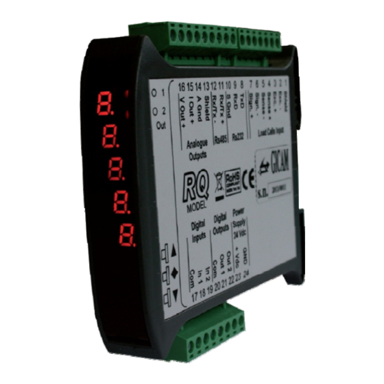
Digital load cell amplifier
Hide thumbs
Also See for RQ:
- Manual (136 pages) ,
- Operational handbook (15 pages) ,
- Installation manual (9 pages)
Table of Contents
Advertisement
Available languages
Available languages
Quick Links
Advertisement
Table of Contents

Subscribe to Our Youtube Channel
Related Manuals for Gicam RQ


Summary of Contents for Gicam RQ
- Page 1 Manuale Manual Handbuch ...
- Page 2 Manuale d’istallazione e d’uso Manuale d’istallazione e d’uso Installa on and user manual Installa on and user manual Installa ons Installa ons – und Bedienungsanleitung und Bedienungsanleitung – AMPLIFICATORE digitale per celle di carico Digital load cell AMPLIFIER Digital VERSTÄRKER für Wägezellen 15/09/2020 ...
-
Page 3: Table Of Contents
Connessione seriale RS232 ........................9 Connessione uscite analogiche (solo versione RQ / ANA) ..............9 Connessione Ethernet (solo versione RQ / Ethernet e RQ / Ethernet IP) ..........10 Connessione ProfiBus (solo versione RQ / ProfiBus) ................11 Connessione ProfiNet (solo versione RQ / ProfiNet) ................11 Connessione Ethercat (solo versione RQ / Ethercat) ................ - Page 4 Serial RS232 connection ........................39 Connection analog outputs (only RQ / ANA version) ................39 Ethernet connection (only RQ / Ethernet and RQ / Ethernet IP versions ..........40 ProfiBus connection (only RQ / ProfiBus version) ................. 41 ProfiNet connection (only RQ / ProfiNet version) .................. 41 Ethercat connection (only RQ / Ethercat version) .................
- Page 5 Serieller RS232 Anschluss ........................69 Anschluss logische Ausgänge (nur Version RQ / ANA) ................ 69 Ethernet Anschluss (nur Versionen RQ / Ethernet und RQ / Ethernet IP) ..........70 ProfiBus Verbindung (nur Version RQ / ProfiBus) ................71 ProfiNet Verbindung (nur Version RQ / ProfiNet) .................. 71 Ethercat Verbindung (nur Version RQ / Ethercat) .................
- Page 6 Bedienungsanleitung ..........................75 Die Frontplatte des Gerätes ........................75 LED Anzeigen ..........................75 Display ............................. 75 Verwendung der Tastatur ........................75 Anzeigen auf dem Display ........................76 Anzeige und Rücksetzen des Gewichts sowie Autotara ............... 77 Umschalten zwischen Netto– und Bruttogewichtsanzeige .............. 77 Umschalten der Anzeige zwischen numerischer / Balkendiagrammanzeige des Bruttogewichts ..
-
Page 7: Manuale D'installazione
Manuale d’installazione Caratteristiche tecniche Alimentazione 24 VCC ± 10 % protetta contro l’inversione di polarità, fusibile ripristinabile Assorbimento Massimo Isolamento Classe II Categoria d’istallazione Categoria II Temperatura di stoccaggio - 20 °C / + 60 °C (- 4 °F / 140 °F) Temperatura di funzionamento - 10 °C / + 50 °C (14 °F / 122 °F), Umidità... -
Page 8: Simbologia
Tutte le connessioni vanno eseguite a strumento spento. Le informazioni seguenti riguardano tutte le funzioni comprese nello strumento RQ, presenti sui vari modelli. Nel riepilogo delle connessioni si notano le funzioni presenti per ogni mo- dello. -
Page 9: Connessione Della Cella Di Carico
Connessione delle celle di carico Eventuali connessioni di prolunga del cavo della devono essere schermate con cura, rispettando il codice colori e utilizzando il cavo del tipo fornito dal costruttore. Le con- nessioni di prolunga devono essere eseguite mediante saldatura, o attraverso morset- tiere di appoggio o tramite la cassetta di giunzione fornita a parte. -
Page 10: Connessione Ingressi Logici (Solo Versione Rq / Ana)
Connessione ingressi logici (solo versione RQ / ANA) Gli ingressi logici sono isolati elettricamente dallo strumento mediante opto-isolatori. I cavi di connessione degli ingressi logici non devono essere incanalati con cavi di potenza o di alimentazione. Usare un cavo di connessione più corto possibile. -
Page 11: Connessione Seriale Rs232
Ricezione dati Massa segnale Connessione uscite analogiche (solo versione RQ / ANA) Lo strumento fornisce un’uscita analogica in corrente e una in tensione con le seguente caratteristiche: Uscita in tensione: range da –10 a 10 Volt oppure da –5 a 5 Volt, carico minimo 10 kΩ... -
Page 12: Connessione Ethernet (Solo Versione Rq / Ethernet E Rq / Ethernet Ip)
Connessione Ethernet (solo versione RQ / Ethernet e RQ / Ethernet IP) Normalmente i cavi sono di tipo “diretto”, e permettono la connessione a dispositivi di rete quali router o hub, ma non di connettere direttamente due PC (anche se attual-... -
Page 13: Connessione Profibus (Solo Versione Rq / Profibus)
Connessione Ethercat (solo versione RQ / Ethercat) Nella versione hardware RQ / Ethercat la connessione alla linea Ethercat viene eseguita tramite due con- nettori RJ45 non intercambiabili. Il connettore verso il panello anteriore è l’ingresso, il connettore verso il retro è l’uscita. -
Page 14: Connessione Devicenet (Solo Versione Rq / Devicenet)
Connessione DeviceNet (solo versione RQ / DeviceNet) Nella versione hardware RQ / DeviceNet la connessione alla linea DeviceNet viene eseguita tramite mor- settiera 5 poli estraibile con le seguente caratteristiche: DeviceNet baud rate 125, 250, 500 kbps Connettore DeviceNet... -
Page 15: Riepilogo Connessioni
Uscita analogica 4-20 mA / 0-20 mA Uscita analogica ± 10 V / ± 5 V A seconda della versione del RQ ordinato (RS485, Analogica, Ethernet, ProfiBUS, ProfiNET, CANopen, DeviceNet) non tutte le connessioni sono disponibile. Connessioni non indicati qui sopra sono realizzate tramite connettori appositi (D-Sub ecc.). -
Page 16: Appunti / Notes / Notizen
Appunti / Notes / Notizen Pagina – page – Seite... -
Page 17: Manuale D'uso
Pressione breve: Commuta visualizzazione numerica / bar-graph del peso lordo Pressione lunga: Azzeramento peso / picco visualizzato Pressione breve: Invio dati su linea seriale (se selezionato protocollo manuale). Pressione lunga: Programmazione soglie (solo hardware RQ / Ana) Premuti contemporaneamente: Accesso al menu principale Pagina –... -
Page 18: Indicazioni A Display
Indicazioni a display All’accensione dello strumento viene eseguito il test dei display, quindi vengono visualizzati in sequenza il E’ importante comunicare questi codici in caso di richiesta di assistenza. Quando non è in corso una procedura di programmazione, il display visualizza il peso rilevato. In determi- nate condizioni vengono segnalati i seguenti messaggi: Segnalazione di Overload Segnalazione di Underload... -
Page 19: Visualizzazione, Azzeramento Peso E Autotara
Visualizzazione, azzeramento peso e autotara All’accensione il display visualizza il peso netto corrente. Commutazione visualizzazione peso netto / peso lordo Premere il tasto per commutare la visualizzazione da peso netto a peso lordo e viceversa. Il valore visualizzato è segnalato dal led superiore (acceso: peso netto). -
Page 20: Funzione Di Picco
Funzione di picco ll valore di picco è riferito al peso lordo e viene 3 sec. 3 sec. calcolato sempre, anche quando la funzione di Azzera picco visualizzazione del picco non è abilitata. Quando la funzione di visualizzazione del picco è abilitata il LED superiore lampeggia. -
Page 21: Menu Di Configurazione Dati Di Pesatura
Menu di configurazione dati di pesatura Contemporaneamente (3 secondi) Torna in visualizzazione peso Portata del sistema di pesatura Impostare il valore corrispondete alla somma delle portate nomi- nali delle celle di carico, valore espresso in kg. Questo dato co- stituisce il valore di fondo scala del sistema di pesatura. -
Page 22: Menu Di Calibrazione Peso
Menu di calibrazione peso Contemporaneamente (3 secondi) Torna in visualizzazione peso Taratura di zero Eseguire questa operazione a bilancia scarica (comprensiva della tara), a peso stabile. Il peso visualizzato si deve azzerare. E’ possibile ripetere più volte questa operazione. Taratura di fondo scala Prima di eseguire questa operazione, caricare sulla bilancia il peso campione e attendere la stabilizzazione, il display visualiz-... -
Page 23: Menu Di Impostazione Parametri Di Pesatura
Menu di impostazione parametri di pesatura Contemporaneamente (3 secondi) Torna in visualizzazione peso Filtro peso Questo parametro permette di regolare l’azione del filtro digitale applicato sul peso rilevato. Il filtro agisce su tutte le rappresenta- zioni del dato peso. Se si programma un valore basso l’azione Imposta valore del filtro è... - Page 24 Torna al menu principale Inseguimento di zero La funzione di inseguimento di zero consiste nell’eseguire auto- maticamente una calibrazione di zero quando il peso subisce una lenta variazione nel tempo, l’intervento dell’inseguimento di Imposta valore zero viene determinato da questo parametro come indicato nella tabella sottostante.
-
Page 25: Menu Di Set-Up Porte Di Comunicazione Seriale
Menu di set-up porte di comunicazione seriale La seriale COM1 RS232 viene sempre gestita, a prescindere dalla versione hardware dello strumento, mentre il funzionamento della seriale COM2 varia a seconda della versione hardware: Contemporaneamente (3 secondi) Torna in visualizzazione peso Protocolli di comunicazione COM1 ... - Page 26 Torna al menu principale Indirizzo di comunicazione seriale COM1 Programmazione dell’indirizzo utilizzato nei protocolli di trasmis- sione del peso e per il protocollo MODBUS, valore impostabile Seleziona valore da 0 a 99. Dato di peso trasmesso COM1 Selezione del valore trasmesso con i protocolli continuo, manua- le ed automatico (vedi relativo paragrafo).
-
Page 27: Protocolli Di Comunicazione Seriale
Protocolli di comunicazione seriale Protocollo trasmissione continuo, automatico e manuale Questi protocolli sono identificati dalle seguenti selezioni (vedi set up delle porte di comunicazione seriale): Continuo (trasmissione continua): CONTN Automatico (trasmissione ad ogni pesata): AUtOM Manuale (trasmissione su comando da tasto o ingresso): dEMAn In questi protocolli viene trasmessa la seguente stringa: <stato>... -
Page 28: Protocollo Trasmissione Slave
Master: <Addr> “P” EOT <Addr> “P” <stato> < > <chksum> EOT picco Comando di autotara Master: <Addr> “A” EOT RQ: <Addr> “A” ACK EOT Comando di zero semiautomatico Master: <Addr> “Z” EOT RQ: <Addr> “Z” ACK EOT Pagina – page – Seite... -
Page 29: Comando Di Reset Valore Di Picco
Comando di reset valore di picco Master: <Addr> “X” EOT RQ: <Addr> “X” ACK EOT Descrizione dei campi I doppi apici (virgolette) racchiudono caratteri costanti (rispettare le maiuscole e le minuscole); i simboli < e > racchiudono campi numerici variabili. -
Page 30: Protocollo Modubs Rtu / Tcp
Protocollo MODBUS RTU / TCP Su COM1 Rs232 è sempre disponibile il protocollo MODBUS RTU. Gli indirizzi riportati nelle tabelle seguono l’indirizzamento standard specificato nella guida di riferimento della Modicon PI-MBUS-300 Rev.J (www.modbus.org). I valori dei registri con indirizzo superiore a 41000 sono memorizzati permanentemente in memoria solo dopo il comando di salvataggio dati. -
Page 31: Elenco Holding Register Protocollo Modbus
Elenco HOLDING REGISTER protocollo MODBUS Indirizzo Holding register 40001 Status register Vedi tabella relativa 40002 Peso lordo (MSB) INT 16 bit 40003 Peso lordo (LSB) INT 16 bit 40004 Peso netto (MSB) INT 16 bit 40005 Peso netto (LSB) INT 16 bit 40006 Picco (MSB) INT 16 bit... -
Page 32: Protocollo Profinet / Ethernet Ip O Ethercat
Protocollo ProfiNet / Ethernet IP o Ethercat Input data area (dati scritti da RQ e letti da Master, Produced Data) 128 byte Registro Indirizzo Holding register 40001 Status register Vedi tabella relativa 40002 Peso lordo (MSB) INT 16 bit 40003... -
Page 33: Output Data Area
Output data area (dati scritti da RQ e letti da Master, Produced Data) 128 byte Registro Indirizzo Holding register 40501 Data register (MSB) INT 16 bit 40502 Data register (LSB) INT 16 bit 40503 Command register Vedi tabella relativa 41001... -
Page 34: Tabella Codifica Status Register
Inserita zero stabile zero I bit 13, 12, 11 ed 10 vengono gestiti solamente in caso di versione RQ / ANA, nelle altre versioni hardware questi bit valgono sempre 0. Tabella codifica command register Funzione command register Funzione data register... -
Page 35: Dati Salvati In Memoria Con Il Comando 0X20
Dati salvati in memoria con il comando 0x20 Indirizzo registro ModBus Descrizione 41001-41002 Portata celle di carico Sensibilità celle di carico 41003 41004 Valore divisione peso 41101 Fattore filtro peso 41102 Fattore stabilità peso 41103-41104 Soglia autozero 41105 Fattore inseguimento zero 41106 Banda di zero 41107... -
Page 36: Guida Alla Risoluzione Dei Problemi
Guida alla risoluzione dei problemi Problema Possibile causa Rimedio Il display visualizza il Il peso acquisito non è rilevabile perché Controllare le connessioni delle celle messagio O-L la cella è assente o collegata erronea- mente Il display visualizza il Il peso acquisito non è rappresentabile trattino alto sul display perché... -
Page 37: Installation Manual
Installation manual Technical specification Power supply 24 VCC ± 10 % protected against reverse polarity, resettable fuse Maximum absorption Insulation Class II Category of installation Category II Storage temperature - 20 °C / + 60 °C (- 4 °F / 140 °F) Operating temperature - 10 °C / + 50 °C (14 °F / 122 °F), Humidity maximum 85% non-condensing Display... -
Page 38: Symbols
All connections must be made with the instrument shut off . The following information pertains to all the functions included in the RQ instrument, present on the various models. In the connections summary you can see the functions present for each model. -
Page 39: Connection Of The Load Cells
Connection of the load cells Any cell cable extension connections must be carefully shielded, respecting the color code and using the cable of the type supplied by the manufacturer. The extension connections must be made by welding, or through support terminal blocks or through the junction box supplied separately. -
Page 40: Logic Inputs Connection (Only Rq / Ana Version)
Logic inputs connection (only RQ / ANA version) The logic inputs are electrically isolated from the instrument by opto-isolators. The logic input connection cables must not be channeled with power or power supply cables. Use a connection cable that is as short as possible. -
Page 41: Serial Rs232 Connection
Data reception Signal mass Connection analog outputs (only RQ / ANA version) The instrument provides an analog current and a voltage output with the following characteristics: Voltage output: range from –10 to 10 Volt or from –5 to 5 Volt, minimum load 10 kΩ... -
Page 42: Ethernet Connection
Ethernet connection (only RQ / Ethernet and RQ / Ethernet IP versions) Normally the cables are of the "direct" type, and allow connection to network devices such as routers or hubs, but not to directly connect two PCs (even if there are current-... -
Page 43: Profibus Connection (Only Rq / Profibus Version)
ProfiNet connection (only RQ / ProfiNet version) In the RQ / ProfiNet hardware version, the connection to the ProfiNet line is executed through the dedicated RJ45 connector. There are two version: with a single RJ45 connector or with two connectors. -
Page 44: Devicenet Connection (Only Rq / Devicenet Version)
DeviceNet connection (only RQ / DeviceNet version) In the RQ / DeviceNet hardware version, the connection to the DeviceNet line is made via a removable 5- pin terminal block with the following characteristics: DeviceNet baud rate 125, 250, 500 kbps... -
Page 45: Connection Summary
Analog output 4-20 mA / 0-20 mA Analog output ± 10 V / ± 5 V Depending on the version of the RQ ordered (RS485, Analog, Ethernet, ProfiBUS, ProfiNET, CANopen, DeviceNet) not all connections are available. Connections not indicated above are made through special connectors (D-Sub etc.). -
Page 46: Appunti / Notes / Notizen
Appunti / Notes / Notizen Pagina – page – Seite... -
Page 47: User Manual
Short press: Switches between numeric / bar-graph display of the gross weight Long press: Reset weight / peak displayed Short press: Send data on serial line (if manual protocol selected). Long press: Programming thresholds (RQ / ANA hardware only) Pressed simultaneously: Access to the main menu Pagina –... -
Page 48: Display Indications
Display indications When the instrument is turned on, the display test is performed, then the software identification code, the It is important to communicate these codes in case of a support request. When a programming procedure is not in progress, the display shows the detected weight. Under certain conditions the following messages are indicated: Overload indication Underload indication... -
Page 49: Weight Display, Reset And Autotare
Weight display, reset and autotare On power up, the display shows the current net weight. Switching between net weight and gross weight display Press the key to switch the display from net weight to gross weight and vice versa. The displayed value is indicated by the upper LED (lit: net weight). -
Page 50: Peak Function
Peak function The peak value refers to the gross weight and is 3 sec. 3 sec. always calculated, even when the peak display Reset peak function is not enabled. When the peak display function is enabled the upper LED flashes. The calculated peak value is 3 sec. -
Page 51: Weighing Data Configuration Menu
Weighing data configuration menu Simultaneously (3 seconds) Return to weight display Capacity of the weighing system Set the value corresponding to the sum of the nominal capaci- ties of the load cells, expressed in kg. This value constitutes the full scale value of the weighing system. -
Page 52: Weight Calibration Menu
Weight calibration menu Simultaneously (3 seconds) Return to weight display Zero calibration Carry out this operation with the scale unloaded (including the tare), with a stable weight. The displayed weight must be reset. It is possible to repeat this operation several times. Full scale calibration Before carrying out this operation, load the sample weight on the scale and wait for stabilization, the display shows the measured... -
Page 53: Weighing Parameters Setting Menu
Weighing parameters setting menu Simultaneously (3 seconds) Return to weight display Weight filter This parameter allows you to adjust the action of the digital filter applied on the detected weight. The filter acts on all the repre- sentations of the given weight. If you program a low value, the Set value filter action is lower while programming a high value the weight is more filtered . - Page 54 Return to main menu Zero tracking The zero tracking function consists of automatically performing a zero calibration when the weight undergoes a slow variation over time, the zero tracking intervention is determined by this Set value parameter as indicated in the table below. To disable the func- tion, set the value 0.
-
Page 55: Serial Communication Ports Set-Up Menu
Serial communication ports set-up menu The COM1 RS232 serial is always managed, regardless of the hardware version of the instrument, while Simultaneously (3 seconds) Return to weight display COM1 communication protocols Serial communication disabled nonE: Contn: Continuous transmission of weight string. It can be Select value used for example to drive a weight repeater display. - Page 56 Return to main menu Serial communication address COM1 Programming of the address used in the weight transmission protocols and for the MODBUS protocol, a value that can be set Select value from 0 to 99. Weight data transmitted COM1 Selection of the value transmitted with continuous, manual and automatic protocols (see relative paragraph).
-
Page 57: Serial Communication Protocols
Serial communication protocols Continuous, automatic and manual transmission protocol These protocols are identified by the following selections (see set up of the serial communication ports): Continuous (continuous transmission): CONTN Automatic (transmission at each weighing): AUtOM Manual (transmission on command from button or input): dEMAn The following string is sent in these protocols: <state>... -
Page 58: Slave Transmission Protocol
Master: <Addr> “P” EOT <Addr> “P” <state> < > <chksum> EOT peak Autotare command Master: <Addr> “A” EOT RQ: <Addr> “A” ACK EOT Semi-automatic zero command Master: <Addr> “Z” EOT RQ: <Addr> “Z” ACK EOT Pagina – page – Seite... -
Page 59: Peak Value Reset Command
Peak value reset command Master: <Addr> “X” EOT RQ: <Addr> “X” ACK EOT Description of the fields The double punctuation marks (quotation marks) enclose constant characters (respect upper and lower case); the symbols < and > enclose variable numeric fields. -
Page 60: Modubs Rtu / Tcp Protocol
MODBUS RTU / TCP protocol On COM1 Rs232 the MODBUS RTU protocol is always available. The addresses shown in the tables follow the standard addressing specified in the Modicon PI-MBUS-300 Rev.J reference guide (www.modbus.org). The values of registers with an address greater than 41000 are stored permanently in memory only after the save data command. -
Page 61: List Holding Register Protocol Modbus
List HOLDING REGISTER protocol MODBUS Address Holding register 40001 Status register See related table 40002 Gross weight (MSB) INT 16 bit 40003 Gross weight (LSB) INT 16 bit 40004 Net weight (MSB) INT 16 bit 40005 Net weight (LSB) INT 16 bit 40006 Peak (MSB) INT 16 bit... -
Page 62: Profinet / Ethernet Ip Or Ethercat Protocol
ProfiNet / Ethernet IP or Ethercat protocol Input data area (data written by RQ and read by Master, Produced Data) 128 bytes Register Address Holding register 40001 Status register See related table 40002 Gross weight (MSB) INT 16 bit 40003... -
Page 63: Output Data Area
The data of the input data area is updated at a frequency of 25 Hz. To transfer the parameters of the Output Data Area to the RQ instrument, direct access to the memory must be enabled, writing the value 0x7FFF in the Command Register (address 40503). -
Page 64: Status Register Coding Table
Band stable center Bits 13, 12, 11 and 10 are only managed in the case of the RQ / ANA version, in the other hardware versions these bits are always worth 0. Command register coding table Command register function... -
Page 65: Data Saved In The Memory With The 0X20 Command
Data saved in the memory with the 0x20 command ModBus register address Description 41001-41002 Load cell capacity Load cell sensibility 41003 41004 Weight division value 41101 Weight filter factor 41102 Weight stability factor 41103-41104 Autozero threshold 41105 Zero tracking factor 41106 Zero band 41107... -
Page 66: Troubleshooting Guide
Troubleshooting guide Problem Possible cause Remedy The display shows the The acquired weight is not detectable Check the connection of the load cell message O-L because the cell is absent or connected incorrectly The display shows the The acquired weight cannot be repre- high dash on the upper sented because it exceeds the five display... -
Page 67: Installationsanleitung
Installationsanleitung Technische Eigenschaften Stromversorgung 24 VDC ± 10% gegen Verpolung geschützt, rücksetzbare Sicherung Maximale Stromaufnahme Isolierung Klasse II Installationskategorie Kategorie II Lagertemperatur - 20 °C / + 60 °C (- 4 °F / 140 °F) Betriebstemperatur - 10 °C / + 50 °C (14 °F / 122 °F), Luftfeuchtigkeit maximal 85% Display Numerisch mit 5 roten LED Anzeigen mit je 7 Segmenten (h 7 mm) 2 LED mit 3 mm (Funktionsstatus) -
Page 68: Symbole
Alle Anschlüsse müssen bei ausgeschaltetem Gerät durchgeführt werden. Die nachfolgenden Informationen beziehen sich auf alle Funktionen des RQ-Verstärkers, die in den verschiedenen Modellen vorhanden sind. In der Anschlussübersicht sehen Sie die Funktionen die in den einzelnen Modellen vorhanden sind. -
Page 69: Anschluss Der Wägezellen
Anschluss der Wägezellen Alle Verlängerungsanschlüsse des Kabels müssen unter Berücksichtigung des Farbcodes und unter Verwendung des vom Hersteller gelieferten Kabels sorgfältig abgeschirmt werden. Die Verlängerungsverbindungen müssen durch Löten, durch Klemmenblöcke oder mit der separat mitgelieferte Anschlussdose hergestellt werden. Das Kabel der Zelle darf nicht mit anderen Kabeln (z. -
Page 70: Anschluss Logische Eingänge (Nur Version Rq / Ana)
Anschluss logische Eingänge (nur Version RQ / ANA) Die Logikeingänge sind durch Optokoppler vom Instrument elektrisch isoliert. Die Verbindungskabel der logischen Eingänge dürfen nicht zusammen mit Leistungs- kabeln oder Stromversorgungskabeln verlegt werden. Verwenden Sie ein möglichst kurzes Anschlusskabel Um einen logischen Eingang zu aktivieren, muss auf an den Pluspol einer 24 Volt Gleichstromversorgung gelegt werden, während die Masse an deren Minuspol angeschlossen werden muss. -
Page 71: Serieller Rs232 Anschluss
Datenempfang Masse Signal Anschluss logische Ausgänge (nur Version RQ / ANA) Das Gerät bietet je einen analogen Strom– und Spannungsausgang mit den folgenden Eigenschaften: Spannungsausgang: Bereich von -10 bis +10 Volt oder von -5 bis +5 Volt, Mindestlast 10 kΩ... -
Page 72: Ethernet Anschluss (Nur Versionen Rq / Ethernet Und Rq / Ethernet Ip)
Ethernet Anschluss (nur Versionen RQ / Ethernet und RQ / Ethernet IP) Normalerweise sind die Kabel vom Typ "direkt" und ermöglichen den Anschluss an Netzwerkgeräte wie Router oder Hubs, jedoch nicht den direkten Anschluss von zwei PCs (selbst wenn derzeit Netzwerkkarten mit Auto-Sensing-Technologie vorhanden sind, die den Kabel-Typ und die Art der Verbindung erkennen, die direkte PC-PC- Verbindungen auch mit nicht überkreuzten Kabeln ermöglichen). -
Page 73: Profibus Verbindung (Nur Version Rq / Profibus)
ProfiNet Verbindung (nur Version RQ / ProfiNet) In der Hardware-Version RQ/ProfiNet erfolgt die Verbindung an die ProfiNet Leitung über einen speziellen RJ45-Anschluss. Es gibt 2 Versionen: mit nur einem RJ45-Anschluss oder mit zwei RJ45-Anschlüssen. Bei zwei Anschlüssen ist der Eingang und der Ausgang der ProfiNet-Leitung gleichgültig. -
Page 74: Devicenet Verbindung (Nur Version Rq / Devicenet)
DeviceNet Verbindung (nur Version RQ / DeviceNet) In der RQ / DeviceNet-Hardwareversion erfolgt die Verbindung zur DeviceNet-Leitung über einen abnehm- baren 5-poligen Klemmenblock mit folgenden Eigenschaften: DeviceNet baud rate 125, 250, 500 kbps 5 poliger DeviceNet Anschluss CAN_L Schirm... -
Page 75: Anschlussübersicht
Analogausgang 4-20 mA / 0-20 mA Analogausgang ± 10 V / ± 5 V Abhängig von der bestellten Version des RQ (RS485, Analog, Ethernet, ProfiBUS, ProfiNET, CANopen, DeviceNet) sind nicht alle Verbindungen verfügbar. Die oben nicht angegebenen Verbindungen erfolgen über spezielle Anschlüsse (D-Sub usw.). -
Page 76: Appunti / Notes / Notizen
Appunti / Notes / Notizen Pagina – page – Seite... -
Page 77: Bedienungsanleitung
Kurzes Drücken: Schaltet die numerische / Balkendiagrammanzeige des Bruttogewichts um Langes Drücken: angezeigtes Gewicht / Spitzenwert zurücksetzen Kurz drücken: Daten auf serieller Leitung senden (falls manuelles Protokoll ausgewählt). Langes Drücken: Programmierung Schwellenwerte (nur RQ / Ana-Hardware) Gleichzeitig gedrückt: Zugriff auf das Hauptmenü Pagina –... -
Page 78: Anzeigen Auf Dem Display
Anzeigen auf dem Display Wenn das Instrument eingeschaltet ist, wird der Anzeigetest durchgeführt, und der Software- Identifikationscode, die relative Version und der Hardwaretyp werden nacheinander angezeigt. Es ist wichtig, diese Codes im Falle einer Service-Anfrage mitzuteilen. Wenn kein Programmiervorgang ausgeführt wird, zeigt das Display das erkannte Gewicht an. Unter be- stimmten Umständen werden folgende Meldungen angezeigt: Überlast-Warnung Unterlast-Warnung... -
Page 79: Anzeige Und Rücksetzen Des Gewichts Sowie Autotara
Anzeige und Rücksetzen des Gewichts sowie Autotara Beim Einschalten zeigt das Display das aktuelle Nettogewicht an. Umschalten zwischen Netto– und Bruttogewichtsanzeige Drücken Sie die Taste um die Anzeige vom Netto- zum Bruttogewicht und umgekehrt umzuschalten. Der angezeigte Wert wird durch die obere LED angezeigt (an: Nettogewicht). -
Page 80: Spitzenwertfunktion
Spitzenwertfunktion Der Spitzenwert bezieht sich auf das Bruttoge- 3 Sek. 3 Sek. wicht und wird immer berechnet, auch wenn die Spitzenwert zurücksetzen Spitzenanzeigefunktion nicht aktiviert ist. Wenn die Spitzenanzeigefunktion aktiviert ist, blinkt die obere LED. Der berechnete Spitzenwert 3 Sek. wird beim Ausschalten nicht beibehalten. -
Page 81: Wiegedaten Konfigurationsmenü
Wiegedaten Konfigurationsmenü Gleichzeitig (3 Sekunden) Zurück zur Gewichtsanzeige Nennlast des Wägesystems Stellen Sie den Wert ein, der der Summe der Nennlasten der Wägezellen, ausgedrückt in kg, entspricht ein. Dieser Wert stellt den Skalenendwert des Wägesystems dar. Werte zwischen 1 Wert einstellen und 9999 werden akzeptiert. -
Page 82: Menü Zur Gewichtskalibrierung
Menü zur Gewichtskalibrierung Gleichzeitig (3 Sekunden) Zurück zur Gewichtsanzeige Nullkalibrierung Führen Sie diesen Vorgang bei unbelasteter Waage (einschließlich Tara) und stabilisiertem Gewicht durch. Das an- gezeigte Gewicht muß zurückgesetzt werden. Der Vorgang kann mehrmals wiederholt werden. Kalibrierung Skalenendwert Bevor Sie diesen Vorgang ausführen, laden Sie das Probenge- wicht auf die Waage und warten Sie auf die Stabilisierung. -
Page 83: Menü Zum Einstellen Der Wiegeparameter
Menü zum Einstellen der Wiegeparameter Gleichzeitig (3 Sekunden) Zurück zur Gewichtsanzeige Gewichtsfilter Mit diesem Parameter können Sie die Wirkung des Digitalfilters auf das erkannte Gewicht einstellen. Der Filter wirkt auf alle Dar- stellungen des angegebenen Gewichts. Wenn Sie einen niedri- Wert einstellen gen Wert programmieren, ist die Filteraktion geringer, während bei einem hohen Wert das Gewicht stärker gefiltert wird. - Page 84 Zurück zum Hauptmenü Nullpunktverfolgung Die Nullpunktverfolgungsfunktion besteht darin, automatisch eine Nullkalibrierung durchzuführen, wenn sich das Gewicht im Laufe der Zeit langsam ändert. Die Nullpunktverfolgung wird Wert einstellen durch diesen Parameter bestimmt, wie in der folgenden Tabelle angegeben. Um die Funktion zu deaktivieren, stellen Sie den Wert 0 ein.
-
Page 85: Einrichtungsmenü Für Serielle Kommunikationsanschlüsse
Einrichtungsmenü für serielle Kommunikationsanschlüsse Die serielle COM1 RS232 wird unabhängig von der Hardwareversion des Instruments immer verwaltet, während der Betrieb der seriellen COM2 je nach Hardwareversion variiert. Gleichzeitig (3 Sekunden) Zurück zur Gewichtsanzeige Kommunikationsprotokolle COM1 Serielle Kommunikation deaktiviert nonE: ... - Page 86 Zurück zum Hauptmenü Serielle Kommunikationsadresse COM1 Programmierung der in den Gewichtsübertragungsprotokollen und für das MODBUS-Protokoll verwendeten Adresse, ein Wert, Wert auswählen der von 0 bis 99 eingestellt werden kann. Übertragener Gewichtswert COM1 Auswahl des mit kontinuierlichen, manuellen und automatischen Protokollen übertragenen Wertes (siehe entsprechenden Ab- Wert auswählen satz).
-
Page 87: Serielle Kommunikationsprotokolle
Serielle Kommunikationsprotokolle Kontinuierliches, automatisches und manuelles Übertragungsprotokoll Die Protokolle werden durch folgende Auswahl gekennzeichnet (s. Einstellungen für serielle Kommunikationsanschlüsse): Kontinuierlich (kontinuierliche Übertragung): CONTN Automatisch (Übertragung nach jeder Wägung): AUtOM Manuell (Übertragung nach Tastaturbefehl oder Eingangsbefehl): dEMAn In diesen Protokollen wird der folgende String übertragen: <status>... -
Page 88: Slave Übertragungsprotokoll
Anforderung aktueller Spitzenwert Master: <Addr> “P” EOT <Addr> “P” <stato> < > <chksum> EOT picco Autotara-Befehl Master: <Addr> “A” EOT RQ: <Addr> “A” ACK EOT Halbautomatischer Nullbefehl Master: <Addr> “Z” EOT RQ: <Addr> “Z” ACK EOT Pagina – page – Seite... -
Page 89: Befehl Zum Zurücksetzen Des Spitzenwertes
Befehl zum Zurücksetzen des Spitzenwertes Master: <Addr> “X” EOT RQ: <Addr> “X” ACK EOT Beschreibung der Felder Die doppelten Hochkommas (Anführungszeichen) enthalten konstante Zeichen (Groß- und Kleinschreibung beachten). Die Symbole <und> schließen variable numerische Felder ein. STX (start of text) = 0x02h, ETX (end of text) = 0x03h, EOT (end of transmission) = 0x04h, ACK (acknowledged) = 0x06h, NAK (Not acknowledged) = 0x15h. -
Page 90: Modubs Rtu / Tcp Protokoll
Für jede Hardwarekonfiguration des Instruments (Rs485, Ana, Ethernet, Profibus, Profinet, DeviceNet, CANopen oder Ethernet IP) ist das MODBUS RTU-Protokoll immer auf COM1 Rs232 verfügbar, bei RQ / Rs485-Hardware ist das MODBUS RTU-Protokoll ebenfalls auf COM2 Rs485 verfügbar . Bei RQ / Ethernet -Hardware kann das MODBUS-TCP-Protokoll über die Ethernet-Schnittstelle des Instruments verwendet... -
Page 91: Liste Holding Register Modbus Protokoll
Liste HOLDING REGISTER MODBUS Protokoll Adresse Holding register 40001 Status register Siehe entsprechende Tabelle 40002 Bruttogewicht (MSB) INT 16-Bit 40003 Bruttogewicht (LSB) INT 16-Bit 40004 Nettogewicht (MSB) INT 16-Bit 40005 Nettogewicht (LSB) INT 16-Bit 40006 Spitzenwert (MSB) INT 16-Bit ... -
Page 92: Profinet / Ethernet Ip Oder Ethercat Protokoll
ProfiNet / Ethernet IP oder Ethercat Protokoll Input data area (Daten von RQ geschrieben und vom Master gelesen, Produced Data) 128 Bytes Register Adresse Holding register 40001 Status register Siehe entsprechende Tabelle 40002 Bruttogewicht (MSB) INT 16-Bit 40003... -
Page 93: Output Data Area
Output data area (Daten von RQ geschrieben und vom Master gelesen, Produced Data ) 128 byte Register Adresse Holding register 40501 Data register (MSB) INT 16-Bit 40502 Data register (LSB) INT 16-Bit 40503 Command register Siehe entsprechende Tabelle 41001 Nennlast Wägezellen (MSB) -
Page 94: Kodierungstabelle Status Register
Nullband fehler Eingestellt Stabil Zentrum Die Bits 13, 12, 11 und 10 werden nur bei der RQ / ANA-Version verwaltet, bei den anderen Hardwareversionen haben diese Bits immer den Wert 0. Kodierungstabelle command register Funktion command register Funktion data register... -
Page 95: Mit Dem Befehl 0X20 Gespeicherte Daten
Mit dem Befehl 0x20 gespeicherte Daten Adresse ModBus Register Beschreibung 41001-41002 Kapazität Wägezellen Empfindlichkeit Wägezellen 41003 41004 Teilungswert Gewicht 41101 Gewichtsfilter Faktor 41102 Gewichtsstabilitäts-Faktor 41103-41104 Schwellenwert Autozero 41105 Faktor Nullpunktverfolgung 41106 Null-Band 41107 Delta Gewicht Kodierungstabelle Teilungswert Registerwert Teilungswert 0,0001 0,0002 0,0005 0,001... -
Page 96: Anleitung Zur Fehlerbehebung
Anleitung zur Fehlerbehebung Problem Mögliche Ursache Lösung Das Display zeigt die Das erfasste Gewicht ist nicht erkenn- Überprüfen Sie den Anschluss der Wä- Meldung O-L an bar, da die Zelle fehlt oder falsch ver- gezelle bunden ist Das Display zeigt den Das erfasste Gewicht kann nicht darge- hohen Strich im oberen stellt werden, da es die fünf verfügbaren... -
Page 97: Appunti / Notes / Notizen
Appunti / Notes / Notizen Pagina – page – Seite... -
Page 98: Appunti / Notes / Notizen
Appunti / Notes / Notizen Pagina – page – Seite... - Page 99 Questo manuale è stato redatto con la massima cura ed al momento della pubblicazione è ritenuto privo di errori. GICAM si impegna di mantenere questo manuale sempre aggiornato e pubblicare versioni aggiornati sul suo sito web appena disponibile. Si declina ogni responsabilità per danni causati da errori in questo momento non identificati e si chiede di segnalare eventuali errori o incongruenze usando i nostri contatti indicati sul retro di questa copertina.
Need help?
Do you have a question about the RQ and is the answer not in the manual?
Questions and answers