Advertisement
Quick Links
®
I-90 ADV & 36V NOZZLE INSTALLATION:
Caution! The riser assembly is under spring
tension. Eye protection should be worn and proper
procedures followed when servicing this product.
Tools needed: Phillips screwdriver, riser service tool
P/N 279600, needle-nose pliers.
Preparation
Unscrew the body cap from the body, then withdraw
the riser from the body. Place the riser assembly's
lower end into the base of riser service tool P/N
279600. Press the tool's metal bar down over the
riser spring until the bar enters the slots in the tool's
base. Rotate the bar to engage with the tool's base,
thereby holding the spring under tension.
Nozzle Removal and Replacement
Remove the logo cap, which is retained by a central
Phillips screw. The nozzle is retained in the nozzle
housing by a setscrew. To remove the nozzle, back
out the setscrew using the hex key on the Hunter
wrench so that the nozzle will clear. Grasp the nozzle
with pliers and pull to remove.
Insert the replacement nozzle in the housing. Press
firmly to fully seat the nozzle so that it will clear the
retaining setscrew. Using the hex key on the Hunter
wrench, turn the setscrew down to retain the nozzle.
Note: When changing from one nozzle number
to another, check the stator for proper setting
before returning the head to service.
Hunter Industries Incorporated • The Irrigation Innovators
1940 Diamond St. • San Marcos, CA 92069 • U.S.A. • www.HunterIndustries.com
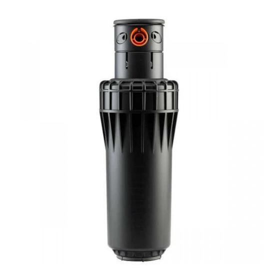
Institutional Series
I-90 Riser Assembly
Retainer Cap
Opening for Nozzle
Riser Assembly
Stator Ring
Filter Screen
STATOR RING INSTALLATION:
Note: When installing nozzles you must also
correctly set the stator to ensure proper
speed of rotation. Failure to correctly set the
stator may cause a non-rotation condition.
The stator is located in the base of the riser
assembly. First remove the riser assembly from
the body. Then remove the filter screen to access
the stator.
The stator has a protruding tab that aligns with a
pointer. Remove the stator by grasping this tab
with pliers and pulling. Replace the stator so that
its pointer is set to the number agreeing with the
nozzle installed. Refer to the Nozzle / Stator Chart
below for nozzle and stator settings.
Visually check for proper assembly of nozzles,
setscrews and stator. Reverse the preparation
procedure to reassemble the unit.
Nozzle / Stator Chart
Nozzle Number
33
38
43
48
53
63
Gear-Driven Sprinklers
Stator Position
33
38
43
48
53
63
© 2002 Hunter Industries Incorporated
P/N 700945
LIT-364
I-90
8/02
Advertisement

Related Manuals for Hunter Institutional Series


Summary of Contents for Hunter Institutional Series
- Page 1 To remove the nozzle, back out the setscrew using the hex key on the Hunter wrench so that the nozzle will clear. Grasp the nozzle with pliers and pull to remove.
- Page 2 The right stop does not change. To Increase Arc: 1. Insert the plastic key end of the Hunter wrench into the adjustment socket (Fig. 1 & 2). 2. While holding the nozzle turret at the right stop, turn the wrench clockwise.
Need help?
Do you have a question about the Institutional Series and is the answer not in the manual?
Questions and answers